

How Should DFM Optimization Be Done for an Inverter Injection Molded Part
Based on the DFM report for an inverter front cover product
Before tooling starts for a front cover plastic part, many issues should not wait until trial molding. Gate vestige, insufficient filling around button areas, parting lines on cosmetic surfaces, sink marks caused by local thick sections, and uneven ejection can all affect appearance and production efficiency.
DFM means design for manufacturing. Its value is to review the product structure, mold structure, and injection molding risks before formal mold machining. The following inverter case shows the key DFM points for this type of injection molded part.
1. Product Conditions Come First
The inverter front cover uses PC/ABS JH980-HT10 material. The general wall thickness is 2.0 mm, the part weight is about 129.5 g, the mold uses a three-plate structure, the cavity layout is 1 x 1, and the recommended molding machine is 300T.
| Item | Content | Item | Content |
|---|---|---|---|
| Product | Inverter | Material | PC/ABS JH980-HT10 |
| General wall thickness | 2.0 mm | Part weight | 129.5 g |
| Mold type | Three-plate mold | Machine tonnage | 300T |
| Gate quantity | 2 + 6 points | Mold life | 500,000 shots |
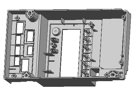
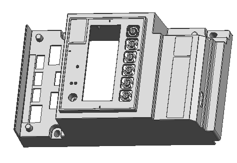
From the product structure, this part has a large main cosmetic surface as well as multiple buttons, ribs, local radii, and assembly-related features. Therefore, the DFM review should not focus on one isolated item. Gate design, parting, draft, wall thickness, ejection, and mold flow analysis need to be considered together.
2. Why the Gate Solution Needs Adjustment
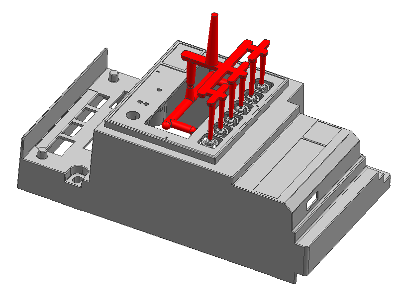
Gate design is critical to stable molding of front cover parts. In the original concept, one local area used a three-plate mold transition to side gating. This created high pressure loss at the gate and made filling on the opposite side more difficult. The gate also required manual trimming, which added labor and could leave visible vestige.
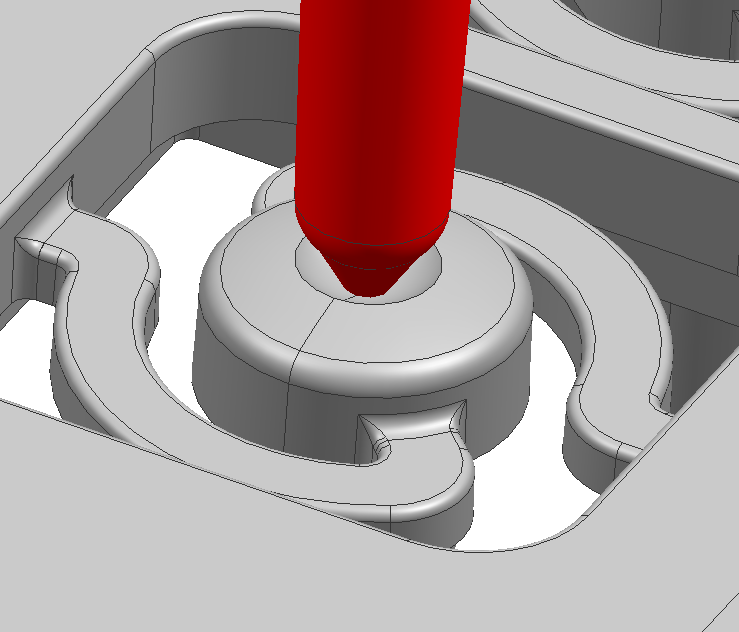
The DFM recommendation is to use two main overlap gates with a gate size of 1 x 8 mm, and to add six independent pin gates for the button positions with a gate size of Ø0.8 mm. This approach brings several practical benefits:
- The main body fills more evenly and reduces one-sided pressure loss.
- The button area receives a dedicated melt path, reducing the risk of short shots in small features.
- Gate vestige can be controlled below 0.3 mm, so the customer can confirm the cosmetic impact in advance.
- The chance of changing the gate after trial molding is reduced, shortening the mold adjustment cycle.
3. Parting Lines and Undercut Areas Should Be Confirmed Early
Front cover products usually have several cosmetic surfaces. Parting lines, slider lines, ejector marks, and insert lines may all affect the customer’s appearance judgment. The DFM report marks these positions so the customer can confirm the acceptable cosmetic range before mold cutting.
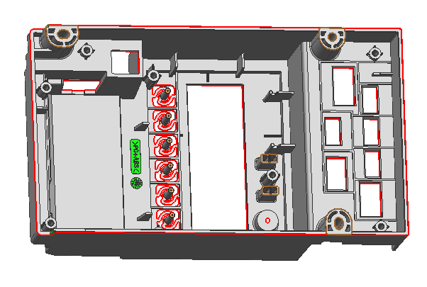
Parting line, slider line, and ejector line review
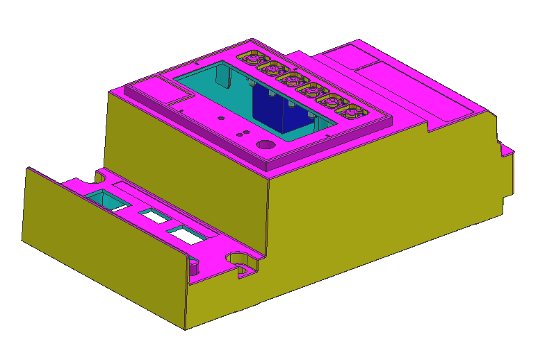
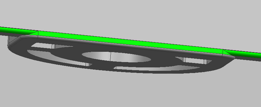
The radii on both side ribs create a parting undercut risk. If this is not addressed, both demolding and appearance can be affected. The proposed solution is to optimize draft along the main arc surface and smooth the undercut around the side R areas, with a local step of about 0.2 mm. Confirming this before tooling helps avoid later rework caused by different appearance expectations.
4. What Problems Can Uneven Wall Thickness Cause
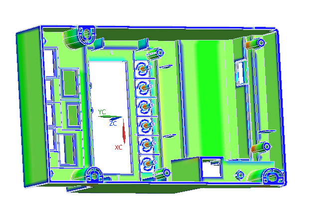
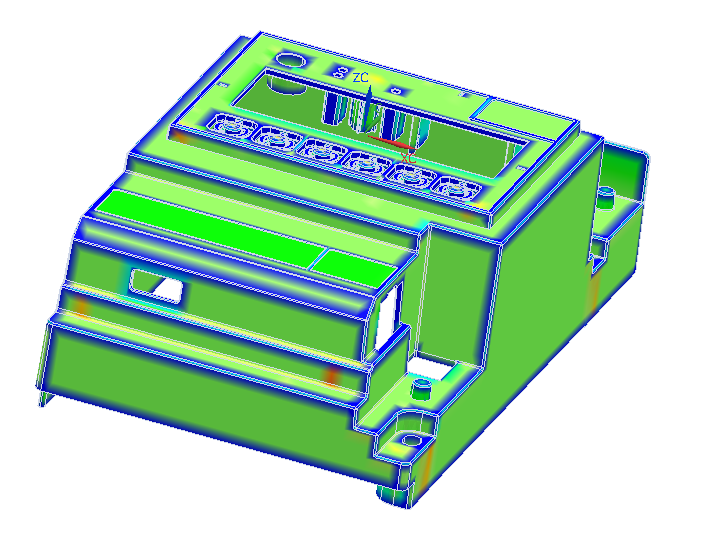
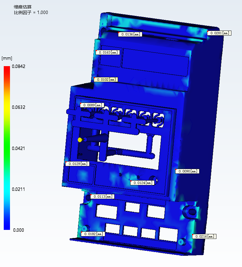
When sink marks appear on plastic parts, process tuning alone often cannot remove them completely. The root cause is usually related to product structure and mold design. The inverter part has uneven local wall thickness, and thick sections carry a slight sink mark risk.
This type of issue should usually be handled from three directions:
- Reduce sudden thick areas in the product structure and make wall transitions smoother where possible.
- Arrange the gates so thick sections receive sufficient packing pressure.
- Coordinate cooling and ejection design to avoid local shrinkage followed by deformation.
5. The Ejection System Is More Than Adding a Few Ejector Pins
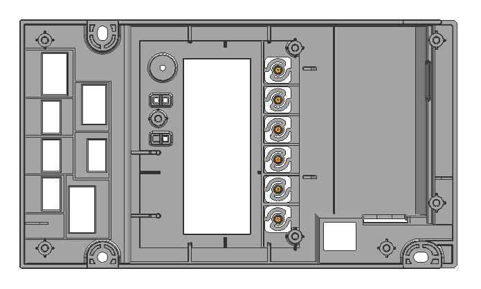
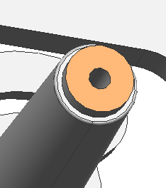
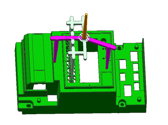
A poorly designed ejection system can cause whitening, raised marks, ejector traces, deformation, or sticking. The report assigns different ejection methods to different areas: blue surfaces use ejector pins, yellow surfaces use ejector sleeves, and the button tips also need additional ejector sleeve support.
This zoned ejection method helps distribute force more evenly and better protects the button tips and local weak structures. For front cover products, the earlier the ejection plan is confirmed, the easier it is to maintain a stable production cycle.
6. What Mold Flow Analysis Can Identify in Advance
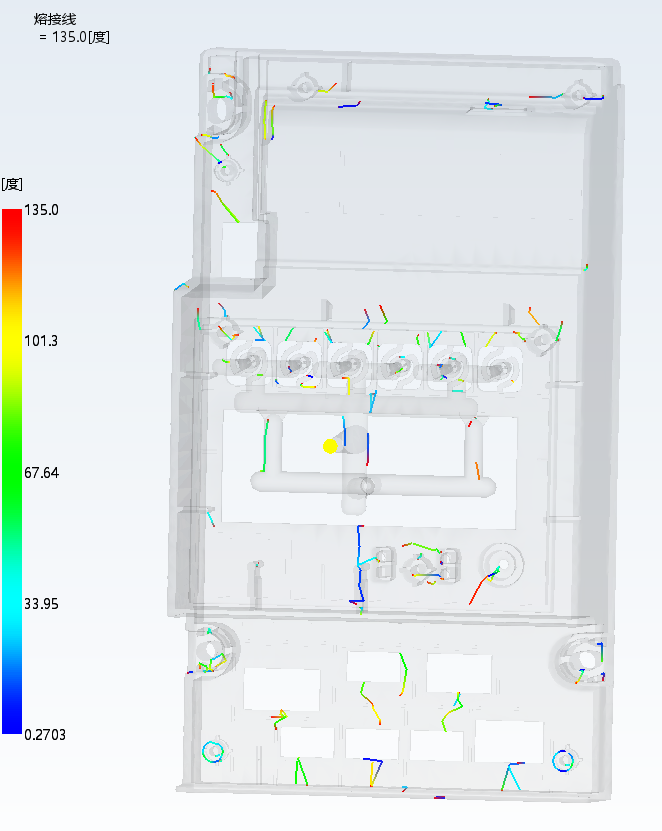
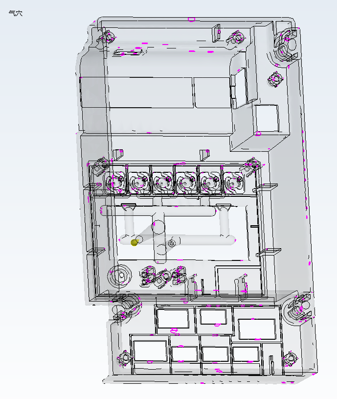
Mold flow analysis mainly checks filling, weld line positions, air traps, and sink mark estimates. It cannot replace trial molding, but it gives engineers a clearer direction before mold machining.
- Filling analysis shows whether the melt can reach remote areas smoothly.
- Weld line analysis helps the customer confirm appearance-sensitive locations early.
- Air trap analysis guides venting positions and reduces burn marks or short shots.
- Sink mark estimation works with wall thickness review to evaluate appearance risk.
7. What Should Be Confirmed Before Tooling This Type of Front Cover Part
Based on this DFM review, the following items should be confirmed before tooling for similar front cover injection molded parts:
- Whether the gate vestige position and height are acceptable.
- Whether the button area needs independent gates to secure filling.
- Whether parting lines, slider lines, and ejector marks affect cosmetic surfaces.
- Whether the step after undercut smoothing meets the appearance standard.
- Whether thick sections require product thinning or process-based packing control.
- Whether ejector pins, sleeves, and blocks avoid appearance-sensitive areas.
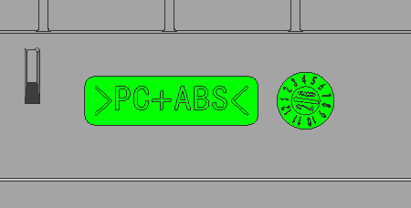
Material marking and date stamp plan
–>
8. The Value of Maifeng’s Solution
A good DFM report does more than list problems. More importantly, it provides a mold solution that can be executed. In this inverter front cover review, Kunshan Maifeng evaluated the gate layout, parting, undercuts, wall thickness, ejection, and mold flow results to turn post-tooling uncertainty into clear design decisions.
For customers, one professional review before tooling means fewer rework risks later. For plastic front covers, housings, button parts, and structural parts, the more complete the DFM review is, the clearer the trial molding direction becomes and the more stable mass production can be.
This is the DFM optimization logic for the inverter front cover injection molded part. If you have similar plastic housings, front covers, button parts, or structural parts that require mold making or injection molding, early-stage DFM review can help move the product closer to stable mass production from the design stage.
Contact Us
📩 Email: Lucie-MF@mold-std.com | 📱 WhatsApp: +86 17714886855
Company Profile

About Us
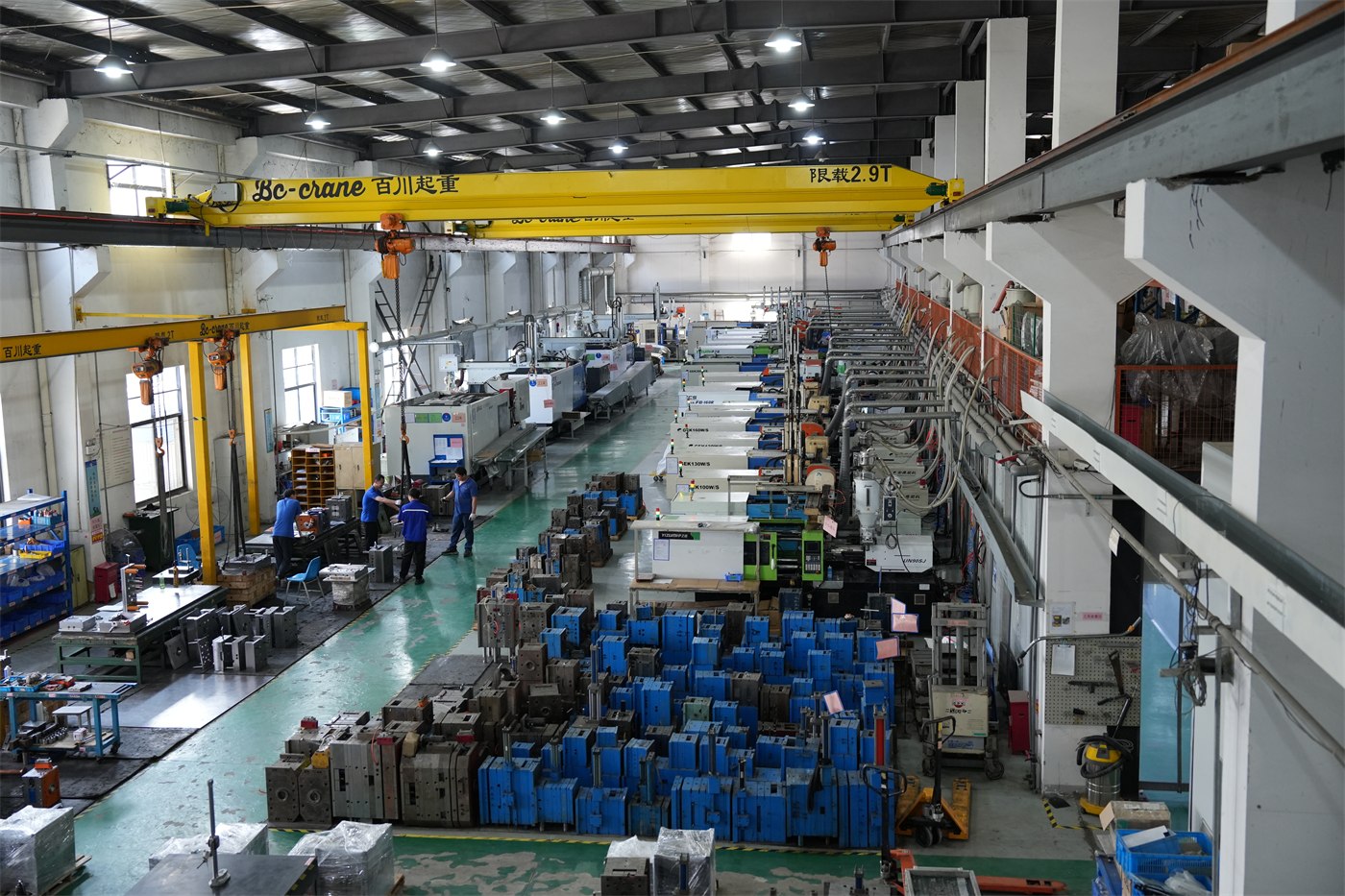
Kunshan Maifeng Precision Industry Co., Ltd. (MIF) has an investment of RMB 35 million and an independent factory of more than 5,000 m². Our manufacturing resources include 36 single- and dual-color injection molding machines from 90 to 700 tons and more than 50 sets of mold manufacturing and processing equipment. Supported by a service, management and production team of over 100 people, we provide product design, mold design and manufacturing, injection molding, and product assembly. Our parent company was established in 2008.
1. Product Design
Product structure design and optimization based on customer drawings and samples.
2. Mold Design
Mold concepts developed around product requirements, material and production needs.
3. Mold Manufacturing
Machining, polishing, assembly and related processes for custom molds.
4. Injection Molding
Single- and dual-color molding capabilities for custom production.
5. Product Assembly



 English
 Chinese