
Nullam dignissim, ante scelerisque the is euismod fermentum odio sem semper the is erat, a feugiat leo urna eget eros. Duis Aenean a imperdiet risus.
Nullam dignissim, ante scelerisque the is euismod fermentum odio sem semper the is erat, a feugiat leo urna eget eros. Duis Aenean a imperdiet risus.
A battery bracket sits inside the base of a portable nasal irrigator, where it does two jobs at once: it locates the cells so they cannot move when the pump vibrates, and it carries the contact geometry that the spring terminals press against. Because the part is buried inside a sealed housing, it is never seen by the user — but any dimensional drift shows up immediately as a rattle, a stiff battery cover, or an intermittent contact.
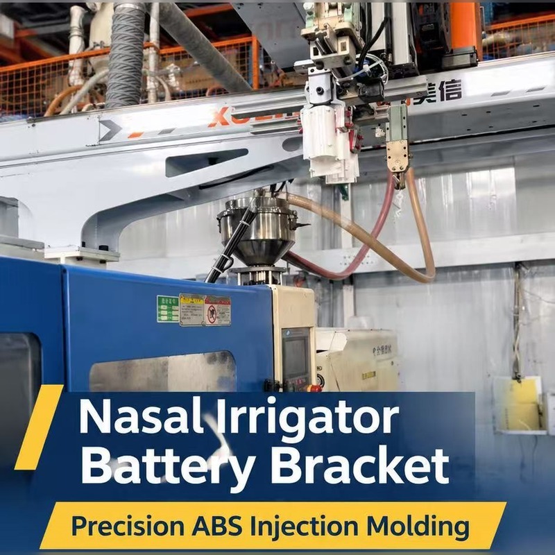
This case covers a white ABS battery holder for a nasal irrigator base: a thin-walled cradle with two locating bosses, a flat seating face and open sides for the cell contacts. The work included the cavity layout, the gate and ejection scheme, a locked molding window, and a trimming and inspection routine for repeat batches. The notes below are the points that decided the outcome.
ABS brings three properties that matter here. It is stiff enough that a 1.8 mm wall keeps its shape around the cell, so the bracket does not bow when the spring terminal pushes back. It moulds to a clean, uniform surface, which makes it easy to see flash, drag marks or contamination on a part that will be handled during assembly. And it holds dimensions well at the wall thickness used here, so cavity-to-cavity variation stays inside the tolerance band that the housing assembly needs.
Two limits are worth stating before the mold is cut. ABS is not the first choice where cells are expected to leak; repeated exposure to alkaline electrolyte will eventually attack it, and PP or a PC/ABS blend is the safer call if leakage is a realistic field condition. ABS is also not suited to steam sterilization — if the device is cleaned with alcohol wipes, that is fine; if it goes into an autoclave, the material has to change. Both questions belong in the design review, not in the first article inspection.
The bracket is mostly thin wall with a few local features, which is the classic recipe for sink marks and short shots. Ribs were kept at roughly 60% of the nominal wall with a fillet at the root, so the rib reinforces the cradle without pulling a shadow onto the outer surface. The two locating bosses are the highest-risk features: a solid boss on a thin wall shrinks from the inside out and leaves a dimple on the opposite face, so the boss wall was thinned, the core pin was cooled, and the boss was tied into a rib rather than standing alone.
The gate was placed on the non-visible end face. That keeps the gate vestige off the surface that faces the housing opening, and it lets the melt front travel along the length of the cradle, which reduces the chance of a weld line landing on a boss. Ejector pins were positioned on the flat seating face and on the rib roots, away from the thin side walls that would otherwise mark or crack.
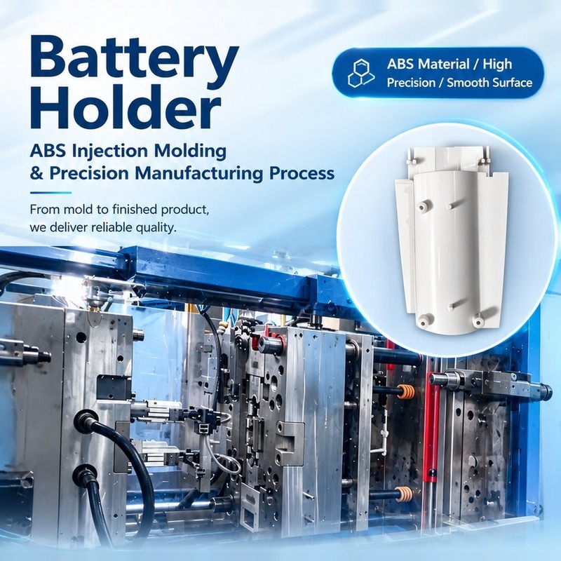
For a part this size the settings are less about filling and more about repeatability. Injection speed, holding pressure and cooling time were fixed per cavity and written onto the setup sheet, and the first-off sample from each run is checked against that sheet before the batch is released. Holding pressure is the parameter that drifts most often on a long run, and on a bracket it shows up as a boss that measures correctly at the start of the shift and undersize at the end.
Demolding is the second risk. The cradle walls are thin enough that a rough ejection will leave white stress marks at the base, which look like cosmetic defects but are really a sign that the part will crack later. Ejection was balanced and the draft on the outer walls was kept generous so the part releases without a fight.
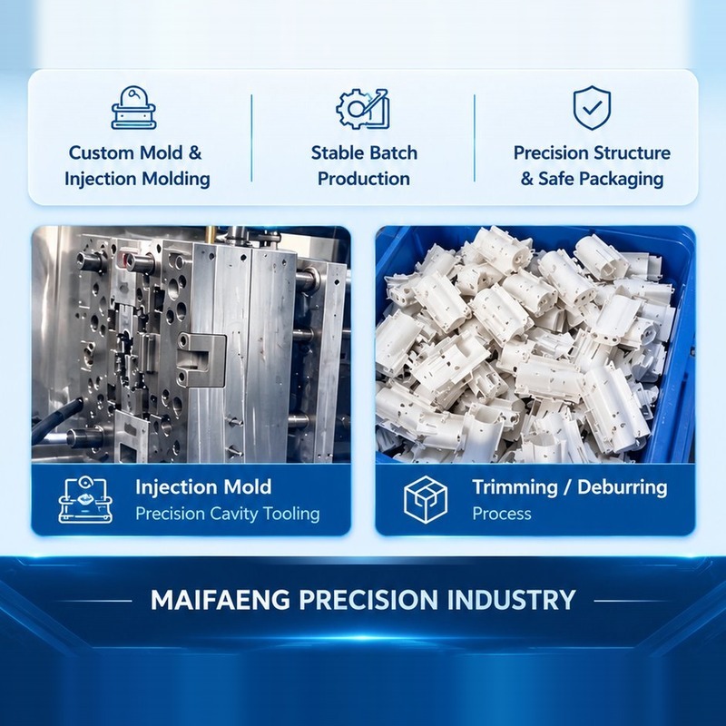
After molding the parts go through trimming and deburring. This is not cosmetic work on a hidden part: a sliver of flash left on the inner cradle face can score the cell wrapper during insertion, and a burr around a contact opening can hold the terminal off its seat. Every part is checked for flash on the internal faces, gate residue, and any drag mark that would indicate a worn cavity edge. A random sample from each batch is measured on the boss spacing, cradle width and seating-face flatness, and the readings are logged against the batch number.
A battery bracket is judged by how it assembles, not by how it measures on a drawing. The two locating bosses have to line up with the housing ribs with enough clearance to drop in by hand but not enough to let the bracket rock, and the seating face has to stay flat so the spring terminal compresses by a predictable amount. We build the sample review around the mating parts: bracket into housing, cells into cradle, cover closed and reopened, contact continuity checked with a meter rather than by eye.
Repeatability across cavities matters as much as the nominal dimension. If the bracket is molded in a multi-cavity tool, the boss spacing on the worst cavity sets the assembly feel for the whole batch, so the tolerance should be allocated per cavity and the sample report should say which cavity each measurement came from. If the part will run for years, the same applies to the steel: cavity edges that wear will show up first as flash on the internal faces, then as a bracket that no longer seats flat.
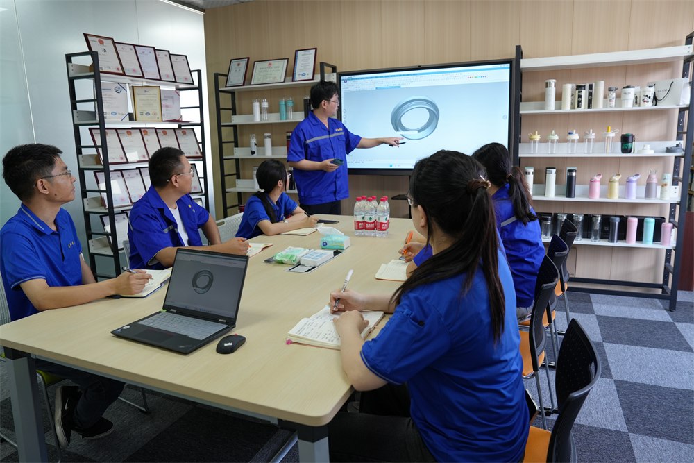
Kunshan Maifeng Precision Industry Co., Ltd. handles product structure review, custom mold design and manufacturing, single- and dual-color injection molding, and plastic part assembly in-house, which means the bracket, its mold and its first-off inspection are all in one place. Send the part drawing, the mating components and the cleaning requirement, and we will come back with a mold concept and a trial plan.
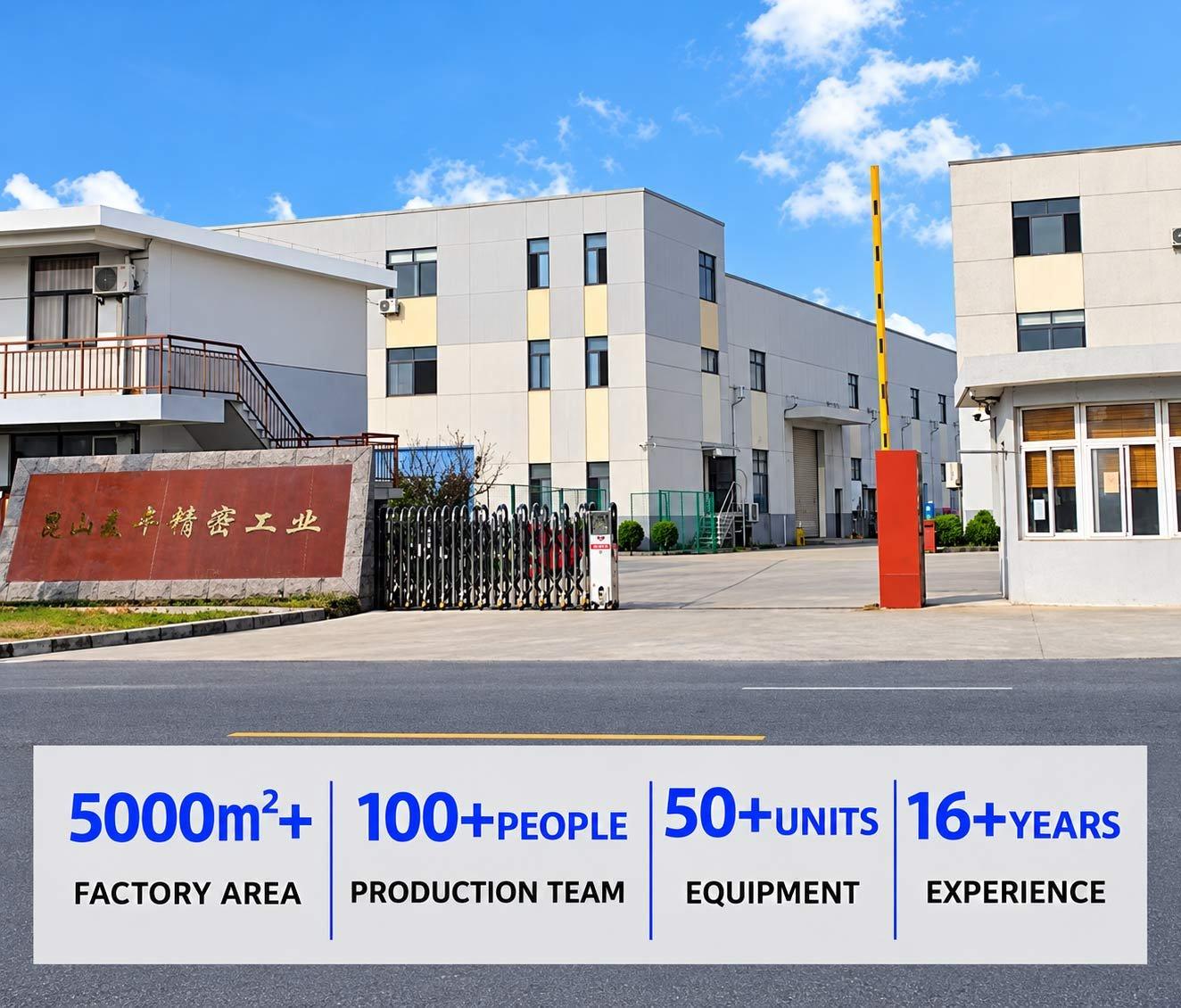
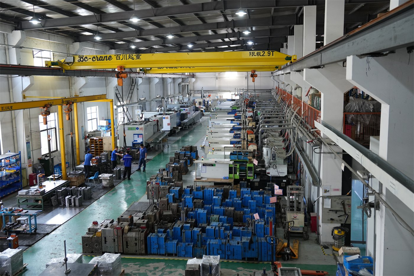
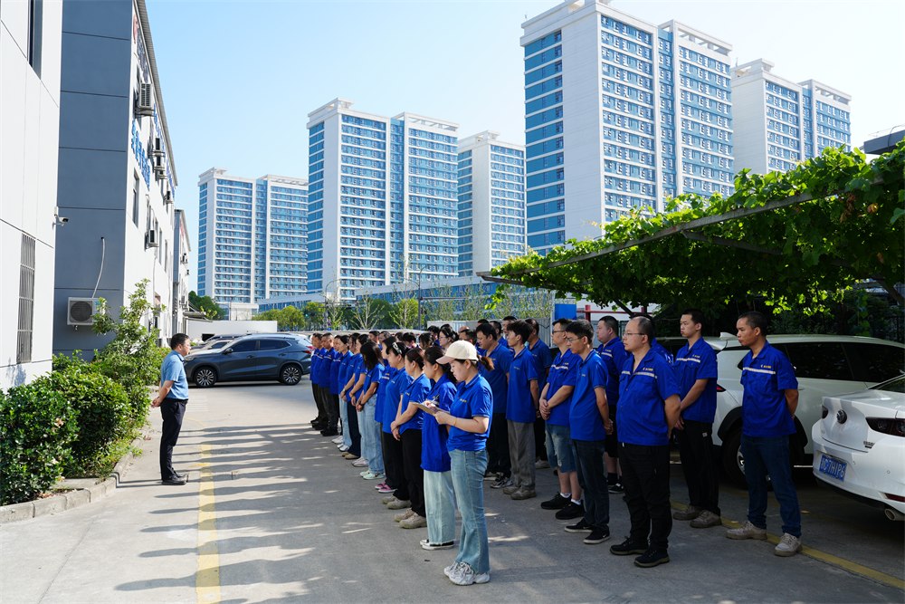
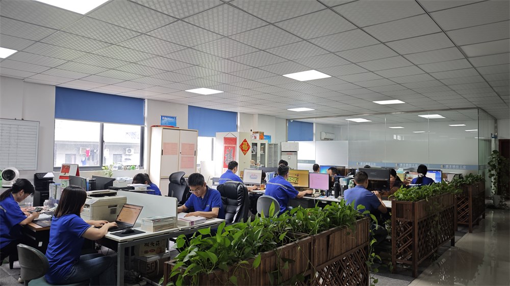
Kunshan Maifeng Precision Industry Co., Ltd. (MIF) has an investment of RMB 35 million and an independent factory of more than 5,000 m². Our manufacturing resources include 36 single- and dual-color injection molding machines from 40 to 700 tons and more than 50 sets of mold manufacturing and processing equipment. Supported by a service, management and production team of over 100 people, we provide product design, mold design and manufacturing, injection molding, and product assembly. Our parent company was established in 2008.
1. Product Design
Product structure design and optimization based on customer drawings and samples.
2. Mold Design
Mold concepts developed around product requirements, material and production needs.
3. Mold Manufacturing
Machining, polishing, assembly and related processes for custom molds.
4. Injection Molding
Single- and dual-color molding capabilities for custom production.
5. Product Assembly




 Chinese
 English