Lawn Mower Tail Light Strip, Clear PC Precision Injection Molded
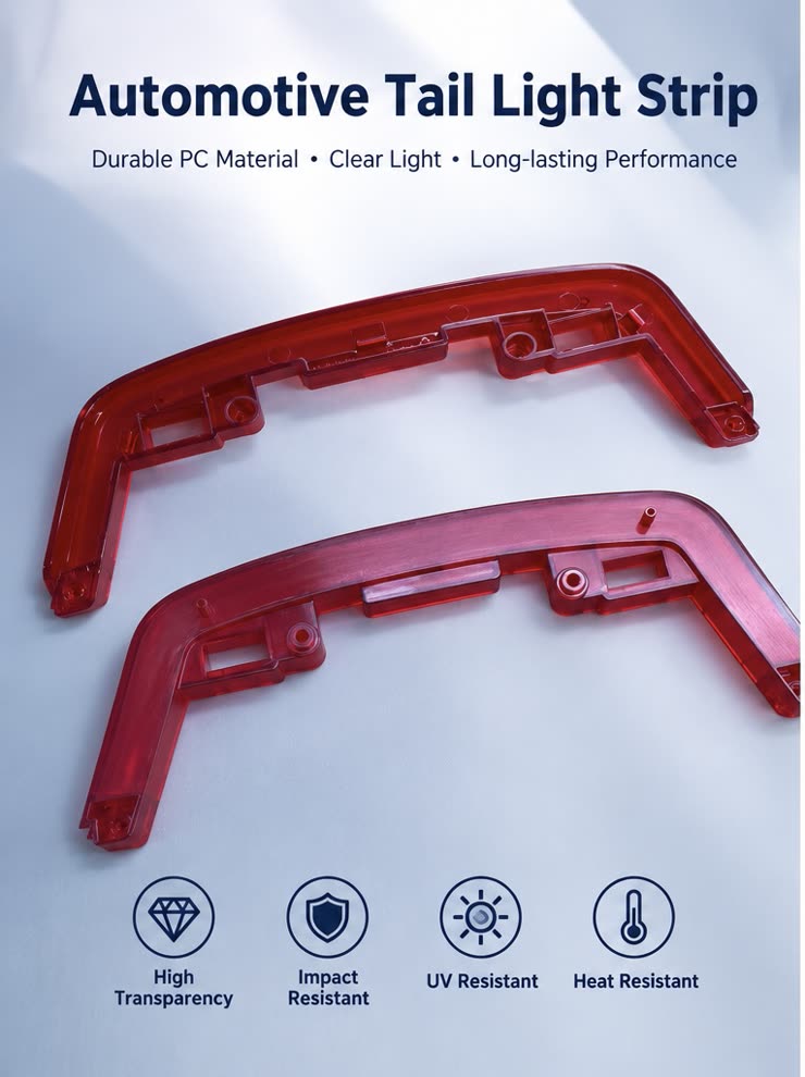
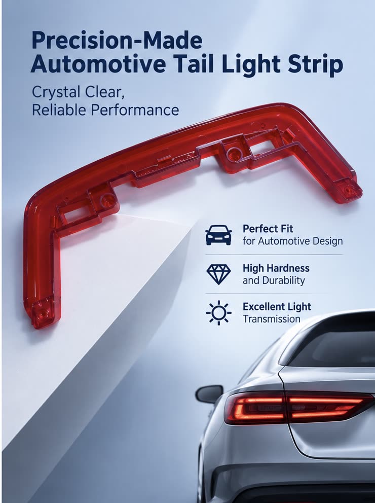
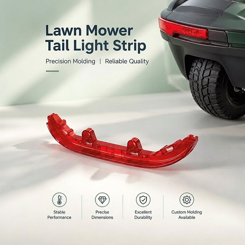
Clear red PC tail light strip molded with a compound curve, four fixing bosses and end clip details, inspected against a light source and packed with separators for assembly.
Clear red PC: light passes the wall evenly, with the impact and UV performance an outdoor deck needs.
Compound curve molded in one shot, with four fixing bosses and end clips formed by slides rather than assembled.
Optical face polished in the direction of light travel, colour held to a retained sample under D65 light.
A tail light strip looks like a simple cosmetic part until you hold one up to a light. Then it is a lens, a light guide and a trim piece at the same time: the wall has to pass light evenly along the whole arc, the curve has to follow the deck of the mower, and the strip has to survive being hit by stones, branches and a pressure washer without cracking or clouding.
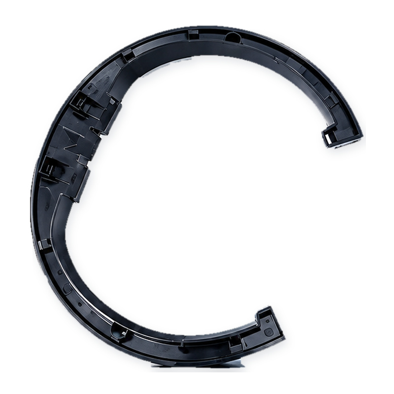
This page is about the part in the photos — a clear red PC strip with a compound curve, four mounting bosses on the back and two clip details at the ends. It comes out of a two-plate mold in one shot, and most of the engineering sits in three places: keeping the wall uniform around the curve, keeping the light path free of flow marks, and keeping the red the same from the first carton to the last.
The strip standing on its end: a compound curve, a clear red PC wall, and the mounting bosses on the back face.
Why PC, and Why the Red Is the Hard Part
Polycarbonate is the default resin for exterior lenses because it does three things at once: it transmits light, it takes an impact without shattering, and it holds its shape when the LED behind it heats the housing. On a mower the impact requirement is not theoretical — the strip sits at deck height, which is exactly where cut grass, gravel and the odd fence post arrive.
The colour is where the process gets difficult. A translucent red is not a paint layer; the shade is the resin itself, and the shade you see depends on how thick the wall is at that point. Where the strip thickens at a boss or a clip, the red reads darker; where the wall thins, it goes orange and the light comes through hotter. That is why the wall is designed to a single nominal thickness around the whole arc, and why the boss bases are thinned into the wall rather than added on top of it.
Two more things decide whether the batch matches the sample. The first is drying: PC absorbs moisture, and moisture in the melt turns into silver streaks that a clear part cannot hide, so the resin runs through a hopper dryer and the first shots of a shift are checked against a light. The second is colour dosing: masterbatch percentage, screw recovery and back pressure all move the shade, so the colour is fixed with a master batch, a locked process sheet and a retained sample under D65 light — not by eye at the machine.
The Curve, the Ribs and the Mounting Bosses
The strip is not a simple arc. It sweeps along the rear of the deck, then turns down at one end, so the mold carries a curved cavity and a core that follows it. Wall thickness is held the same through the bend; where the section changes from the flat run into the downturn, the transition is radiused so the flow front does not stall and leave a hesitation mark right where the light is brightest.
The back face is busier than the front: four bosses for the fixing screws, clip hooks at the ends, and a shallow rib that stiffens the middle of the run. Ribs are kept to roughly half the wall thickness and are placed behind the mounting points rather than behind the middle of the light path, because a rib that is too heavy pulls a sink mark into the visible face and a sink mark in a clear red part is impossible to polish out. Bosses get draft and a fillet at the base for the same reason: the load at the screw has to spread into the wall without a thick section that shrinks late.
Front and back of the same strip: the light path stays clean on one side, the bosses, ribs and clip details sit on the other.
Light, Not Just Shape
A clear part is judged by what it does with light, and that is decided before the steel is cut. The gate goes at one end, outside the lit zone, so the gate vestige and the flow marks that follow it sit where the LED never reaches. Filling is balanced so the flow front reaches both ends of the arc at the same time; if one end fills first, the last section to fill traps air and leaves a short or a dull patch.
Weld lines are the other optical defect. Where two flow fronts meet, the material is weaker and the surface scatters light, so the meeting point is pushed to the end of the strip behind the end clip. The cavity is polished in the direction of light travel rather than across it, and no texture is applied inside the lit area: a texture that hides flow marks on an opaque part turns a clear lens milky.
The result is checked the way a customer will see it — with the LED behind it, not on a white table. If the strip is meant to read as a continuous line of light, the check is for bright and dark bands along the arc; if it is only a reflector, the check is colour and gloss. Both are written into the inspection sheet before production starts, because “looks fine” is not a specification.
The L-shaped version of the same family: same wall rule, same polish direction, a tighter bend to mold.
The Tool: Cavity, Slide and Polish
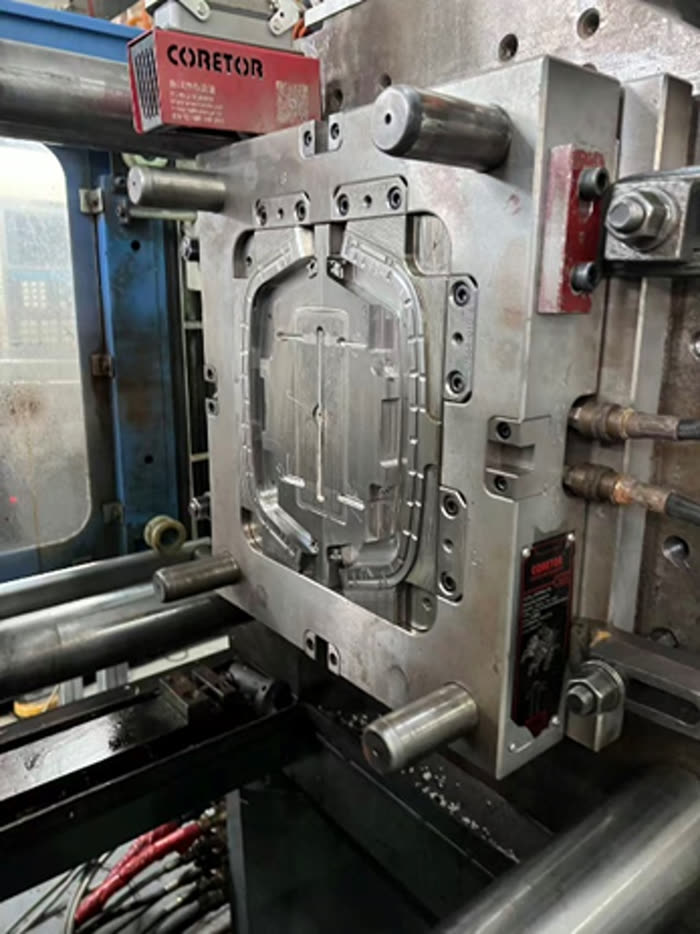
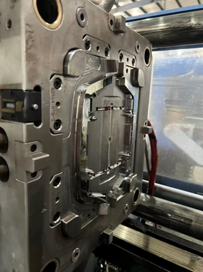
The mold is a single-cavity tool for this size of part, built in house. The cavity block carries the polished optical face; the core side carries the bosses and ribs, with slides for the clip details at the ends that cannot be stripped in the opening direction. Cooling follows the arc in both halves — a curved line of baffles in the core and a matching circuit in the cavity — because a clear part cools visibly: uneven cooling leaves a wave of orientation stress that shows up as a haze band under the light.
Ejection is on the bosses and the end faces, never on the optical wall. The polish grade on the lens face is specified on the drawing (SPI A-2 or better for a lit lens), and the tool is re-polished at service intervals rather than only when it scratches, because a polished face that has gone slightly dull is exactly what makes a clear part look yellow after a year outdoors.
Cavity block: the optical face is polished before the tool is assembled.Core side: bosses, ribs and the slides that form the end clips.
From the Press to the Carton
Parts come out hot and are handled by the edges only, because a fresh PC lens marks if it is picked off the face while it is still soft. They are laid on a soft-lined tray to cool flat rather than tipped into a bin, and the first parts of each shift go to the bench for a light check before anything is packed.
Packing is where a good part usually gets damaged. Strips are separated from each other — tissue or a moulded tray — so the polished faces never rub in transit, and they ship in a carton that a customer can open at the assembly line without cutting into the parts. Where the customer assembles with a robot, the tray pitch is agreed in advance, not invented at the packing table.
The finished strips on the bench: light passing through the wall with no streaks, the mounting holes and ribs on the back face, and the mold that produces them.
What Is Checked Before the Strip Is Packed
Arc and profile — the strip is laid on a profile gauge cut to the drawing; the gap along the deck edge is measured at three points, not judged by eye.
Boss positions — centre distances and height of the four mounting bosses, since these decide whether the strip pulls down flat and whether the clip engages.
Wall and section — thickness at the thin sections with an ultrasonic gauge; a wall that runs thin loses light and a wall that runs thick goes dark red.
Colour — against the retained sample under D65 light, with the customer’s colour chip if they have one.
Light output — with the specified LED behind it: bright and dark bands, haze, silver streaks, and any flow mark crossing the lit zone.
Appearance and fit — sink marks on the visible face, gate vestige, flash at the parting line, and a trial fit on the customer’s housing where the tool allows it.
Lying flat on the bench: the bosses and ribs are on the back, the light path stays clean.
What Can Be Customized
Almost everything except the physics. The strip can be re-drawn to a different arc or length, the section can be thickened where the customer’s deck vibrates, the clip and boss layout can be moved to suit an existing housing, and the colour can be matched to a chip — clear, red, amber or a tinted smoke. Lens texture, if the customer wants a diffused look, is applied outside the critical light path or over the whole face with the diffusion agreed against a light sample.
What we will push back on is a strip designed with a heavy rib directly behind the light path, or a wall that changes thickness by more than about 20 percent along the arc. Both are moldable, and both will show — the first as a sink mark, the second as a colour band. It is cheaper to change the drawing than to re-polish a tool.
Information to Confirm Before Starting a Tail Light Strip Project
3D model and drawing of the strip, plus the mating housing or deck surface, so the clip and boss positions can be checked against something real.
Optical requirement — is this a lit lens, a light guide, or a reflector? That decides polish grade, gate position and the inspection method.
The LED behind it — type, position and power, which set the colour density and the heat the strip has to live with.
Colour standard — a chip, a Pantone reference or a physical sample, and the light source it will be judged under.
Environment — UV exposure, cleaning chemicals, stone impact, and any automotive or outdoor-power-equipment standard the part has to pass.
Annual volume and packaging — which decides cavity count, tray design and whether automation at the customer’s line is worth designing for.
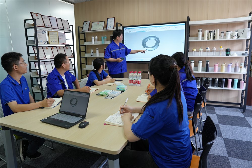
Kunshan Maifeng Precision Industry Co., Ltd. reviews the drawing and the optical requirement before quoting, builds the injection mold in house, and molds clear and coloured PC on 36 machines from 40 to 700 tons. Send us the 3D model of the strip with the LED position and the colour target, and we will come back with a feasibility comment, a tooling proposal and the inspection plan we would run on the first article.
Contact Us
Lucie — Kunshan Maifeng Precision Industry Co., Ltd.
Custom Mold • Precision Injection Molding • Consistent Production. Send us the 3D model of the strip and the colour target, and we will come back with a tooling proposal.
Company Profile
About Us
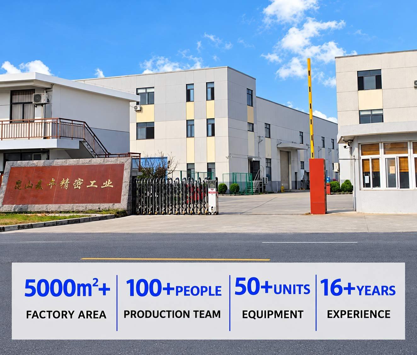
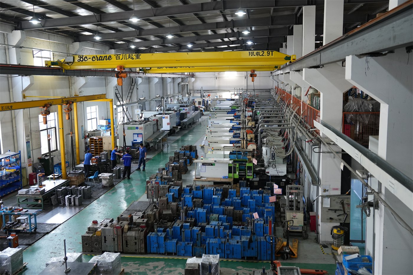
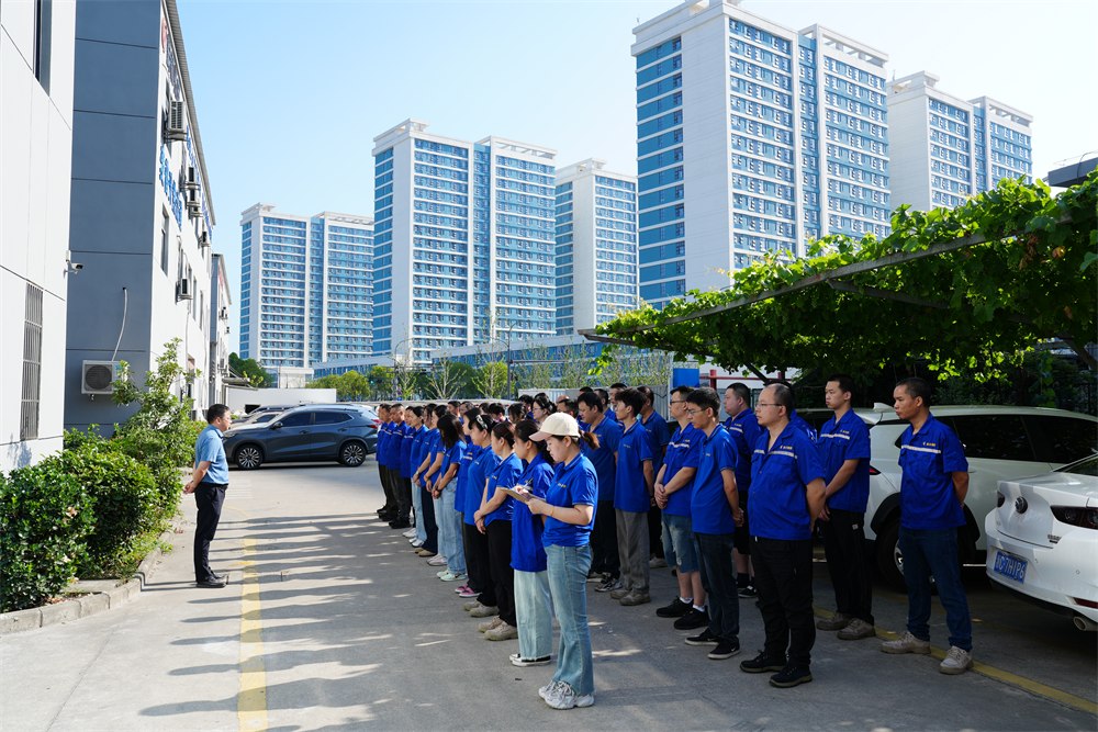
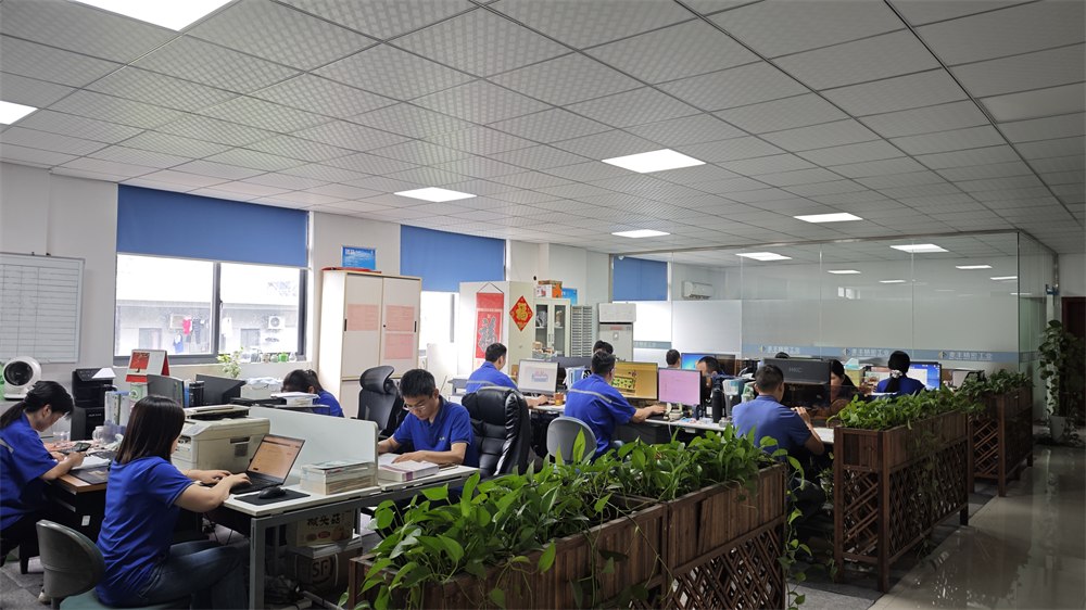
Kunshan Maifeng Precision Industry Co., Ltd. (MIF) has an investment of RMB 35 million and an independent factory of more than 5,000 m². The company operates 36 single- and dual-color injection molding machines from 40 to 700 tons, together with more than 50 sets of mold manufacturing and processing equipment. Our service, management and production team includes over 100 people.
Our parent company was established in 2008. We provide product design, mold design and manufacturing, injection molding and product assembly services for custom plastic parts, supporting both domestic and international customers.
1. Product Design Product structure design and optimization based on customer drawings and samples.
2. Mold Design Mold design developed around product geometry, material and production requirements.
3. Mold Manufacturing Machining, polishing, fitting and assembly for custom injection molds.
4. Injection Molding Single- and dual-color injection molding for project and order requirements.
5. Product Assembly Supporting assembly services for molded plastic components.
Custom glossy black PC protective cover for lawn mowers: an open-ring shell with snap clips molded in one shot and a class-A face that survives stones, sun and cleaning.
Custom PC light-diffusion tail light grille for lawn mowers: an even light band, a ribbed outer face, a sealed fixing flange and an optical surface finished to the agreed polish.
PC+ABS automotive wireless charging housing with an open coil window, four mounting ears and a stiffening rib, molded, inspected and packed for console assembly.
PC lawn mower tail light grille produced through custom mold development, precision injection molding and strict quality control for demanding outdoor applications.
PP handles and plastic parts for a 3rd generation magnetic wall mounted toilet brush, produced at Maifeng Precision through custom mold design, injection molding and careful inspection.
ABS nasal irrigator outer housing produced with custom multi-cavity molds, precision injection molding, careful trimming and dust-free packaging for personal care brands.
ABS nasal irrigator base produced with custom mold design, precision injection molding, strict inspection and dust-free packaging for personal care and medical device assemblies.
No matter what your automotive needs may be, we’re here to help. Contact us today to learn more about our
services and how we can assist you with all of your needs.
ISO 13485-certified medical injection molding in Class 10,000/100,000 cleanrooms: 36 single and dual-color machines, proven medical cases and trusted partners.
One-stop cup and bottle molding: dual-color lids, tea-separation cups and handles, QS food-contact licensed production with proven cases for global brands.
Contact Us
To grow into a top global mold & injection molding supplier
To grow into a top global mold & injection molding supplier, specializing in differentiated custom parts. We focus on structural development, streamlined production and consistent quality supply.









 Chinese
 English