Auto Transmission Shift Knob, Injection Molded Car Gear Handle Component
This shift knob is an assembly of three moldings: the silver shell, satin painted after molding and cured before assembly; the gloss black top panel with gear positions printed on its underside so the markings sit behind the wear surface; and the integrated P button in a spring-captured guided bore. A textured geometric grain at the front face is molded, not printed. In the base, a steel sleeve moulded in place carries the square drive hole and release windows, so latch torque never loads the plastic alone. Sleeve concentricity to the knob axis is held and verified against the actual lever geometry on first articles.
gear markings printed behind the clear gloss panel where thumbnails cannot reach the ink
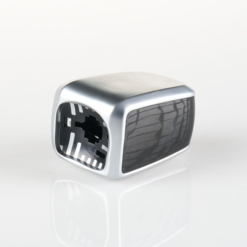
steel sleeve moulded into the base takes the latch torque instead of the plastic
three-part assembly — shell, panel, button — mated and checked as one part in house
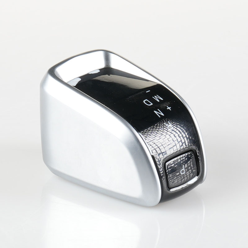
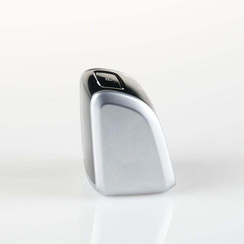
This is the shift knob of an automatic transmission selector. The silver body is a molded shell finished in a satin metallic paint, the top panel is a separate gloss black molding carrying the printed gear positions — M, D, N, R with plus and minus for manual mode — and the P button sits integrated at the front, over a textured face panel. Underneath, a steel sleeve with a square drive hole receives the lever head, so working torque passes through steel rather than the plastic around it.
Three moldings and a print operation make one knob. This page covers how the parts come together, how the markings survive years of fingers, and what we need confirmed before quoting.
Front view: the integrated P button over the textured face panel.
How the Three Moldings Become One Knob
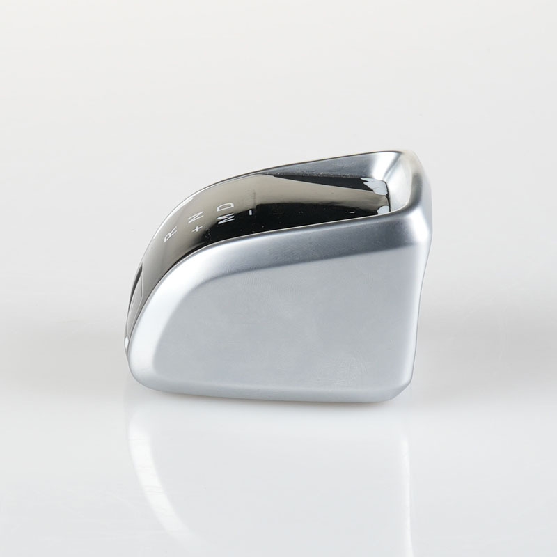
The silver shell carries the shape a hand actually grips — a soft-sided wedge, narrow at the top, rounded everywhere a palm lands. Its satin finish is paint, applied after molding and cured before assembly, because a plated part at this wall thickness would show sink at the heavy corners. The gloss black top panel is its own molding, snapped into the shell opening; the trim between them is the shadow line that hides the joint.
The P button loads into a guided bore in the top panel with its spring captured underneath, so the button travel is set by the mold, not adjusted at assembly. The button is the highest-wear feature on the part — pressed several times a day for the life of the car — and its bore is dimensioned so it cannot stick even with dust in the guides.
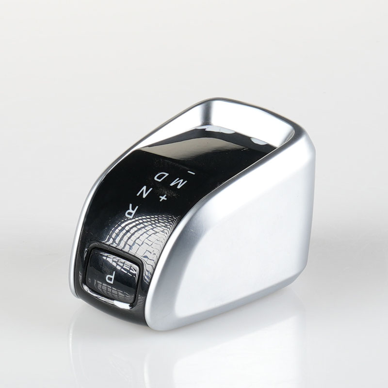
The gear positions printed on the gloss top panel.
Gear Markings That Stay Legible
The gear letters are printed on the underside of the clear gloss panel, not on its surface. Printed behind the resin, they sit under the wear surface — a thumbnail scraping across the panel cannot reach the ink. The print is aligned to the panel in a fixture, checked against the lever’s detent positions, because a letter off by a degree reads as a fault in the whole transmission. Alignment to the panel is a first-article item; alignment to the detents is the customer’s assembly check.
The textured face at the front is a mold texture, not print: a fine geometric grain molded into a separate dark panel. It survives exactly as long as the plastic does, which is the right answer for a surface at fingertip height.
The satin silver shell from the rear, paint-cured before assembly.
The Steel Sleeve at the Bottom
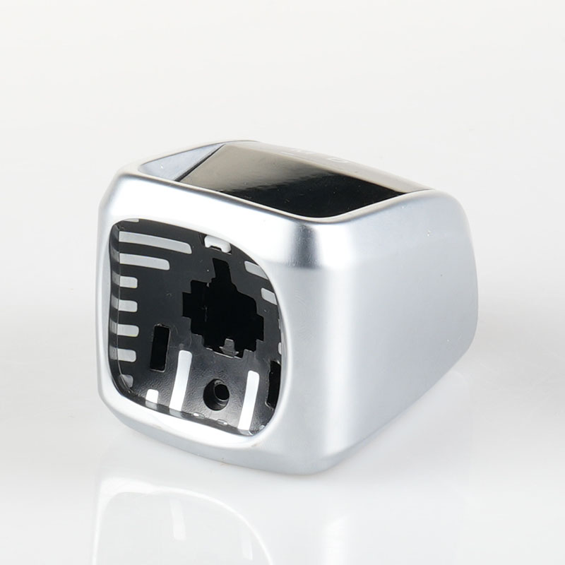
Every shift knob in service takes its whole working load through one feature: the socket that seats on the lever. Here that socket is a steel sleeve, molded in. The square drive hole matches the lever’s latch head, and the slots around the sleeve are the release windows the tool engages to pull the knob off for service. Plastic alone would creep under the repeated latch torque and eventually crack at the corners of the square; the sleeve moves that failure out of the part’s life.
The sleeve is positioned in the mold to the knob’s centre axis and held there during molding — an insert feature whose concentricity to the outer body decides whether the knob sits square on the lever. It is checked on first articles with the actual lever geometry, not just measured in isolation.
The moulded-in steel sleeve and its square drive hole.
Information to Confirm Before Starting a Shift Knob Project
The lever head drawing — square size, latch windows and seat height set the sleeve.
The gear position sequence and which markings light up or print.
Button travel and spring rate, or the switch it carries if the P button is live.
Colour and finish standard for the painted shell, with a cured sample for approval.
Annual volume, since the paint line is scheduled per batch, not per piece.
Kunshan Maifeng Precision Industry Co., Ltd. molds shift knobs and comparable multi-part interior components in house — shell, panel and button from three tools, assembled and checked as one part on machines from 90 to 700 tons. Send us the lever head drawing and the marking layout, and we will come back with a structure proposal and a tooling quotation.
Company Profile
About Us
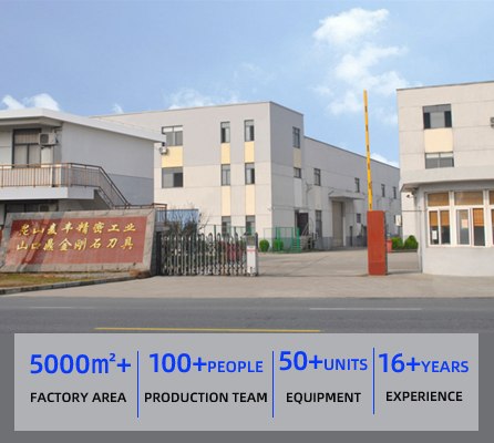
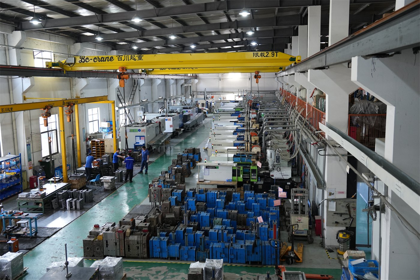
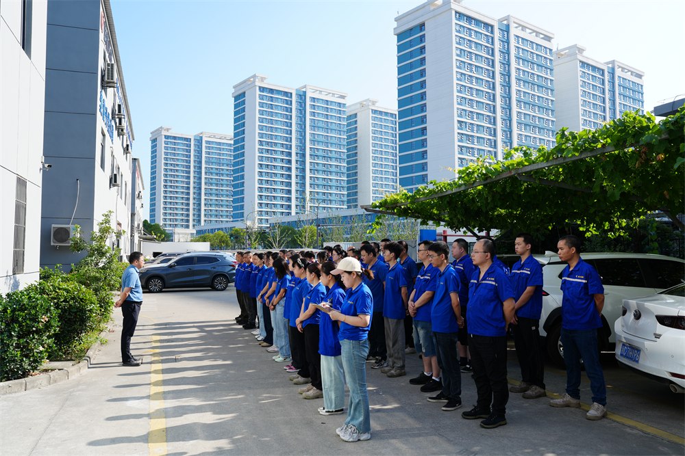
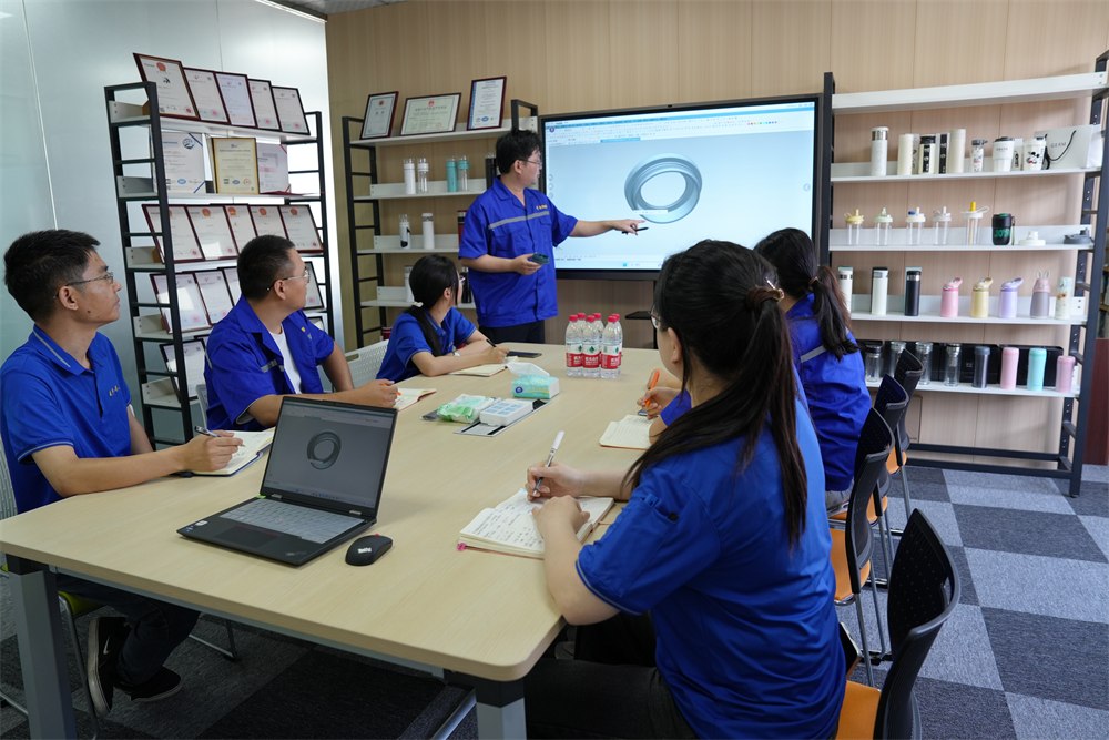
Kunshan Maifeng Precision Industry Co., Ltd. (MIF) has an investment of RMB 35 million and an independent factory of more than 5,000 m². The company operates 36 single- and dual-color injection molding machines from 90 to 700 tons, together with more than 50 sets of mold manufacturing and processing equipment. Our service, management and production team includes over 100 people.
Our parent company was established in 2008. We provide product design, mold design and manufacturing, injection molding and product assembly services for custom plastic parts, supporting both domestic and international customers.
1. Product Design Product structure design and optimization based on customer drawings and samples.
2. Mold Design Mold design developed around product geometry, material and production requirements.
3. Mold Manufacturing Machining, polishing, fitting and assembly for custom injection molds.
4. Injection Molding Single- and dual-color injection molding for project and order requirements.
5. Product Assembly Supporting assembly services for molded plastic components.
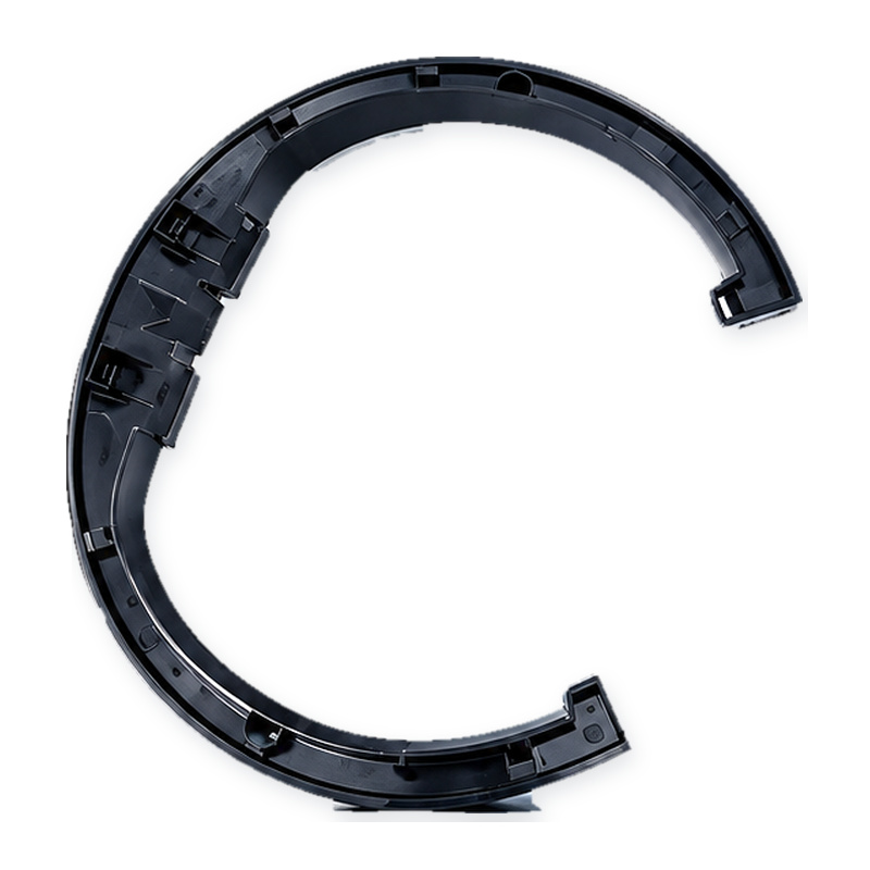
Custom glossy black PC protective cover for lawn mowers: an open-ring shell with snap clips molded in one shot and a class-A face that survives stones, sun and cleaning.
Custom PC light-diffusion tail light grille for lawn mowers: an even light band, a ribbed outer face, a sealed fixing flange and an optical surface finished to the agreed polish.
Custom clear PC tail light strip for mowers and outdoor equipment: compound curve, uniform wall, polished optical face and colour matched to your chip.
PC+ABS automotive wireless charging housing with an open coil window, four mounting ears and a stiffening rib, molded, inspected and packed for console assembly.
PC lawn mower tail light grille produced through custom mold development, precision injection molding and strict quality control for demanding outdoor applications.
PP handles and plastic parts for a 3rd generation magnetic wall mounted toilet brush, produced at Maifeng Precision through custom mold design, injection molding and careful inspection.
ABS nasal irrigator outer housing produced with custom multi-cavity molds, precision injection molding, careful trimming and dust-free packaging for personal care brands.
ABS nasal irrigator base produced with custom mold design, precision injection molding, strict inspection and dust-free packaging for personal care and medical device assemblies.
No matter what your automotive needs may be, we’re here to help. Contact us today to learn more about our
services and how we can assist you with all of your needs.
ISO 13485-certified medical injection molding in Class 10,000/100,000 cleanrooms: 36 single and dual-color machines, proven medical cases and trusted partners.
One-stop cup and bottle molding: dual-color lids, tea-separation cups and handles, QS food-contact licensed production with proven cases for global brands.
Contact Us
To grow into a top global mold & injection molding supplier
To grow into a top global mold & injection molding supplier, specializing in differentiated custom parts. We focus on structural development, streamlined production and consistent quality supply.







 English
 Chinese