Router Top Cover Panel, Plastic Housing Accessory for Network Device
This router top cover panel is precision injection molded in one piece, with a dense field of heat dissipation micro holes arranged in rows for even melt feeding during molding. Eight oval gasket seats and a larger antenna pass-through are moulded to position, and snap fingers around the border engage the mating base without fasteners. The smooth appearance side carries printed function marks. Wall thickness and cooling are balanced against warp on this thin, wide panel. Hole pattern, gasket layout, resin and colour can be adapted to a customer housing design.
dense hole field moulded in rows so the melt feeds evenly and hole edges stay burr-free
eight gasket seats and the antenna pass-through moulded to position, repeatable across the run
edge clips and ribs sized from the mating base, not from the panel drawing alone
A router top panel carries more than its looks suggest. The field of small holes across it lets convection move warm air out of the enclosure, the black gasket seats keep dust and fingers out of the antenna openings, and the whole cover has to snap onto the base in seconds on an assembly line without flexing or creaking. The panel shown here does all three in one moulded piece.
The part is moulded from a light grey resin as a single shot. The hole array, the oval gasket seats, the larger oval cutout and the snap features along all four edges come out of the tool together; nothing is drilled or trimmed afterwards. Four views of the finished panel are shown below, two per side.
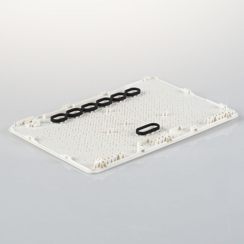
Inner face of the panel. The hole field runs in neat rows, and the eight oval gasket seats sit toward one end.
Moulding a Panel Full of Holes
Several hundred small holes in a thin panel sounds routine until you build the tool. Every hole is a core pin standing in the melt path, and every pin is a place where the part can hang up on ejection or pick up a burr. The pins are short, which helps, but their tips form the visible face of the panel, so any wear or damage in the steel shows up on every shot.
Hole quality is the acceptance point. A ragged edge reads as a defect even from a metre away, and a partially blocked hole quietly reduces airflow. The holes are arranged in rows rather than at random, which keeps the melt feeding evenly between them; a scattered pattern forces the flow to split and rejoin repeatedly, and each split is a chance for a short shot at the far edge of the panel.
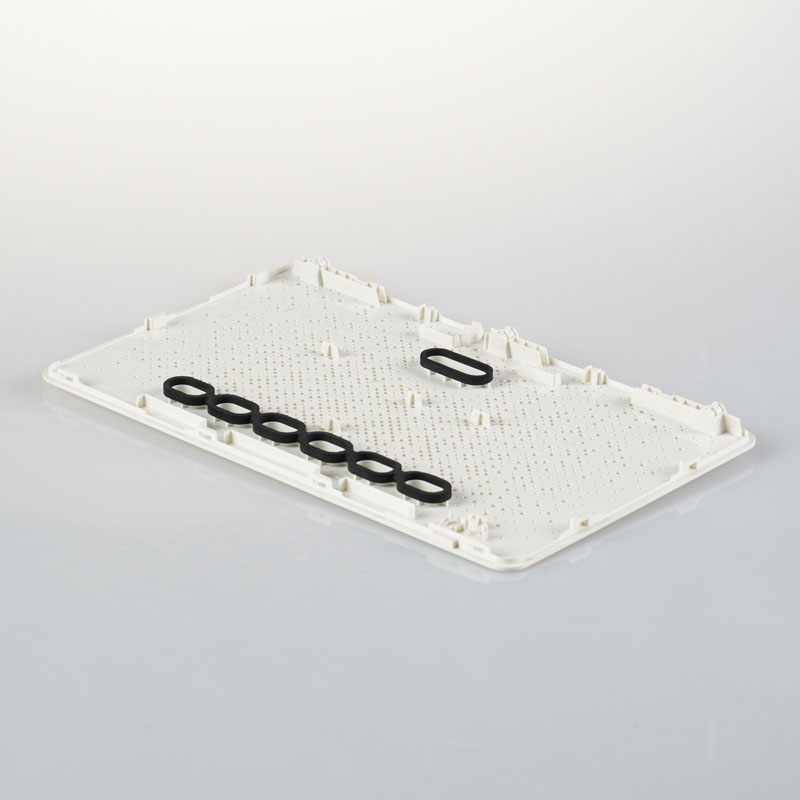
Angled view of the inner face. The oval cutout and the moulded clips around the border are clearly visible.
Gasket Seats and the Antenna Pass-Through
The eight oval seats take rubber gaskets, and the larger oval cutout clears the antenna assembly. Neither is just a hole in the drawing. The gasket seat needs a defined depth and a lip for the rubber to sit against, or the seal leaks and dust works its way into the enclosure over time. The pass-through needs to be positioned so the antenna connector reaches it without strain once the board is in place.
Because the seats are moulded rather than machined, their positions come from the tool and repeat across the production run. On an assembly line that matters: a gasket seat half a millimetre out of position turns into intermittent fit problems that are far more expensive to trace than to prevent.
Keeping a Thin, Wide Panel Flat
The panel is wide relative to its thickness, which is the classic recipe for warp. Uneven cooling between the two faces, or a packing profile that leaves residual stress near the gate, shows up as a dish or a saddle across the panel. A warped top cover either refuses to snap down cleanly or sits with a visible gap at one corner of a router that is meant to look square.
The countermeasures are ordinary but have to be held: uniform wall away from the reinforced border, balanced cooling around the cavity, and enough cooling time that the part has stopped moving before ejection. The dense hole field actually helps here, breaking up what would otherwise be a large uninterrupted surface.
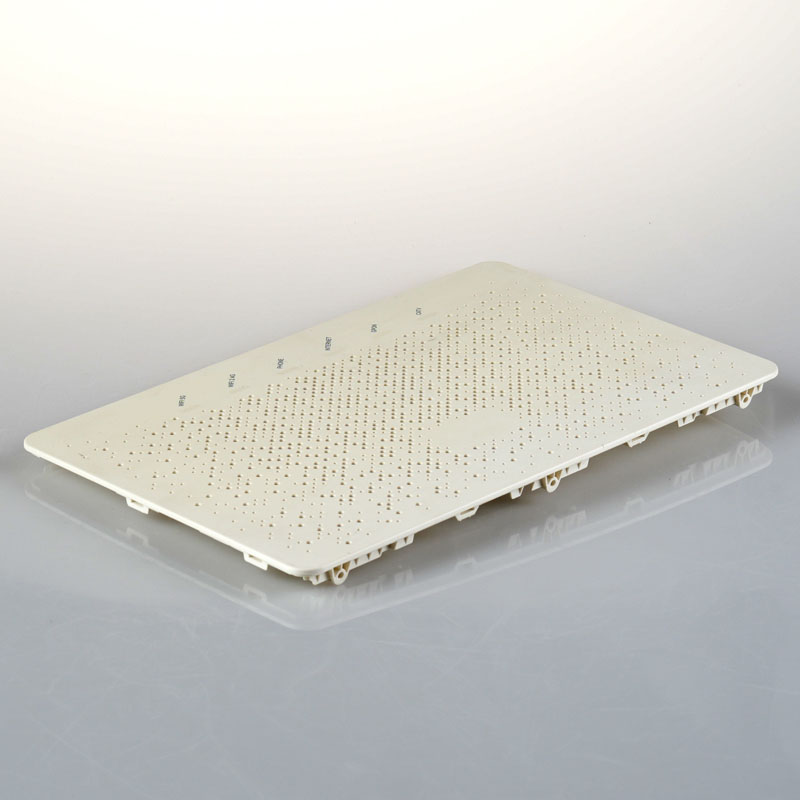
Outer face of the panel. The appearance side stays smooth, with the function marks printed after moulding.
Clips, Posts and Assembly Fit
The border carries the working features: snap fingers along the edges, positioning posts on the inner face, and ribs that stiffen the panel without thickening the appearance surface. A thin cover stiffened only by its own thickness would either flex under a hand pressing it or need so much thickness that sink marks would show around every feature on the visible side.
The snap geometry is set by the mating base, not by this panel alone. Clip engagement depth, the angle of the lead-in and the retention force all come from the assembly drawing, which is why we ask for the base housing rather than the panel alone when quoting. A cover that clips too loosely rattles; one that clips too tightly cracks at the corner when a technician pops it off for service.
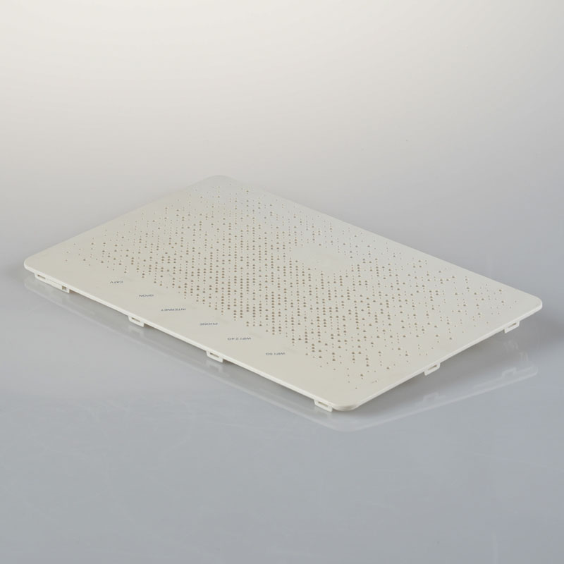
The panel laid flat. The edge clips and the smooth outer face are both visible from this angle.
What Gets Checked Before the Panels Ship
Flatness across the panel, checked on a surface plate. Hole quality, inspected under magnification on a sample from each lot for burrs and blocked holes. Gasket seat depth and position, verified with the actual rubber gasket in place. Clip retention force, measured against the agreed value rather than judged by hand. Colour and surface finish matched against the approved master, since a visible top panel sits right next to the base it has to match.
Information to Confirm Before Starting a Router Cover Project
The mating base housing drawing, since clip positions, engagement depth and the antenna pass-through all depend on it.
The hole pattern and open-area requirement, so the array can be laid out to feed evenly during moulding.
Resin and colour specification, including any flame-retardant grade the destination market requires.
Whether function marks are printed after moulding or moulded in, and who supplies the artwork.
Annual volume and the number of colour variants, which set the cavity count and tooling budget.
Kunshan Maifeng Precision Industry Co., Ltd. reviews enclosure and cover panel designs before quoting, builds the injection molds in house, and molds single-color and dual-color parts on 36 machines from 90 to 700 tons. Send us the base housing drawing and the hole pattern requirement, and we will come back with a feasibility comment and a tooling proposal.
Company Profile
About Us
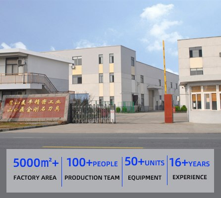
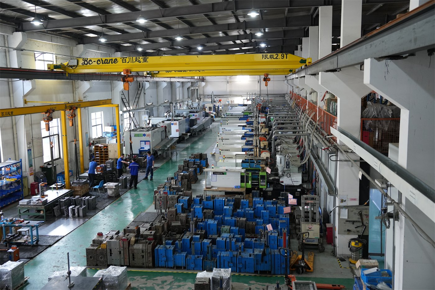
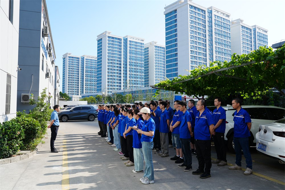
Kunshan Maifeng Precision Industry Co., Ltd. (MIF) has an investment of RMB 35 million and an independent factory of more than 5,000 m². The company operates 36 single- and dual-color injection molding machines from 90 to 700 tons, together with more than 50 sets of mold manufacturing and processing equipment. Our service, management and production team includes over 100 people.
Our parent company was established in 2008. We provide product design, mold design and manufacturing, injection molding and product assembly services for custom plastic parts, supporting both domestic and international customers.
1. Product Design Product structure design and optimization based on customer drawings and samples.
2. Mold Design Mold design developed around product geometry, material and production requirements.
3. Mold Manufacturing Machining, polishing, fitting and assembly for custom injection molds.
4. Injection Molding Single- and dual-color injection molding for project and order requirements.
5. Product Assembly Supporting assembly services for molded plastic components.
Custom glossy black PC protective cover for lawn mowers: an open-ring shell with snap clips molded in one shot and a class-A face that survives stones, sun and cleaning.
Custom PC light-diffusion tail light grille for lawn mowers: an even light band, a ribbed outer face, a sealed fixing flange and an optical surface finished to the agreed polish.
Custom clear PC tail light strip for mowers and outdoor equipment: compound curve, uniform wall, polished optical face and colour matched to your chip.
PC+ABS automotive wireless charging housing with an open coil window, four mounting ears and a stiffening rib, molded, inspected and packed for console assembly.
PC lawn mower tail light grille produced through custom mold development, precision injection molding and strict quality control for demanding outdoor applications.
PP handles and plastic parts for a 3rd generation magnetic wall mounted toilet brush, produced at Maifeng Precision through custom mold design, injection molding and careful inspection.
ABS nasal irrigator outer housing produced with custom multi-cavity molds, precision injection molding, careful trimming and dust-free packaging for personal care brands.
ABS nasal irrigator base produced with custom mold design, precision injection molding, strict inspection and dust-free packaging for personal care and medical device assemblies.
No matter what your automotive needs may be, we’re here to help. Contact us today to learn more about our
services and how we can assist you with all of your needs.
ISO 13485-certified medical injection molding in Class 10,000/100,000 cleanrooms: 36 single and dual-color machines, proven medical cases and trusted partners.
One-stop cup and bottle molding: dual-color lids, tea-separation cups and handles, QS food-contact licensed production with proven cases for global brands.
Contact Us
To grow into a top global mold & injection molding supplier
To grow into a top global mold & injection molding supplier, specializing in differentiated custom parts. We focus on structural development, streamlined production and consistent quality supply.






 English
 Chinese