Car Taillight Light Guide Assembly, High Transmittance Injection Lamp Accessory
This taillight light guide assembly is molded clear in one shot from a high-transparency resin. Two lens-shaped blades are linked by a curved transparent arm, and the ribbed surface spreads the LED light along the blade instead of leaving a bright spot at one end. Positioning posts and clips come out of the same shot, so the guide sits a fixed distance from the LED on every part. The assembly is molded for taillight signal lamp use, and blade profile, rib pattern and post layout can be adjusted to a customer housing.
high-transparency resin with controlled flow keeps the lit blade even from end to end
ribbed optical surface spreads LED output along the blade rather than piling it up at one point
molded posts and clip features hold assembly position shot after shot
A taillight light guide has one job: take the light from an LED at one end and spread it along a blade long enough to be seen from behind the car. The part shown here does that with two lens-shaped guides linked by a curved transparent arm. Nothing on it is painted, plated or printed. It is molded clear from start to finish, and the only reason it works is that the resin, the surface texture and the wall thickness are all held under control.
Both blades and the connecting arm come out of the same tool in a single shot. The positioning posts and clip features are molded in place as well, so the assembly drops straight into the lamp housing without a secondary operation. What follows covers the resin choice, the ribbed surface that does the light spreading, the tooling problems specific to long thin clear parts, and what gets checked before the parts are packed.
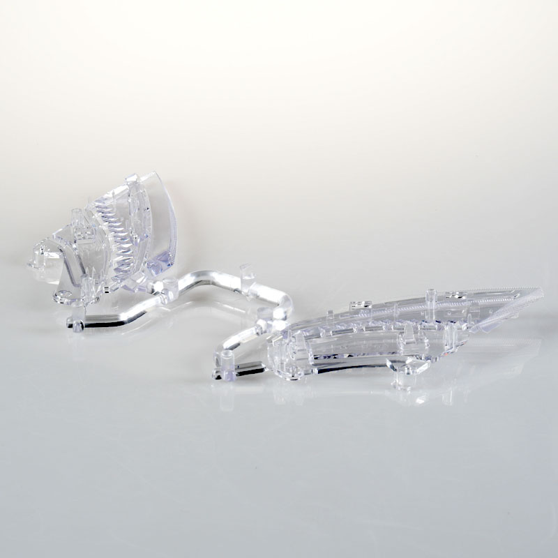
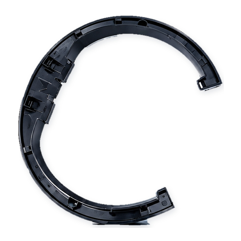
Overall view of the taillight light guide assembly: two ribbed blades linked by a curved transparent arm.
Choosing the Resin for a Light Guide
PMMA and optical-grade PC are the two usual candidates. PMMA transmits roughly 92 percent of visible light and holds up better against long-term UV exposure, which matters for a part mounted on the rear of a vehicle. PC is tougher and shrugs off impact and rough handling during assembly, but it yellows sooner unless a UV stabilizer is compounded in. Which one gets used comes down to where the lamp sits, how the guide is clipped in, and whether the customer carries a weathering specification.
Clarity is not the only property under scrutiny. Flow marks, black specks and moisture streaks that would never be noticed in a black housing part are all visible in a clear one. The resin has to be dried to spec before molding, and the regrind ratio is kept low or zero, because a small amount of contaminated regrind shows up in a lamp part long before it would show up anywhere else.
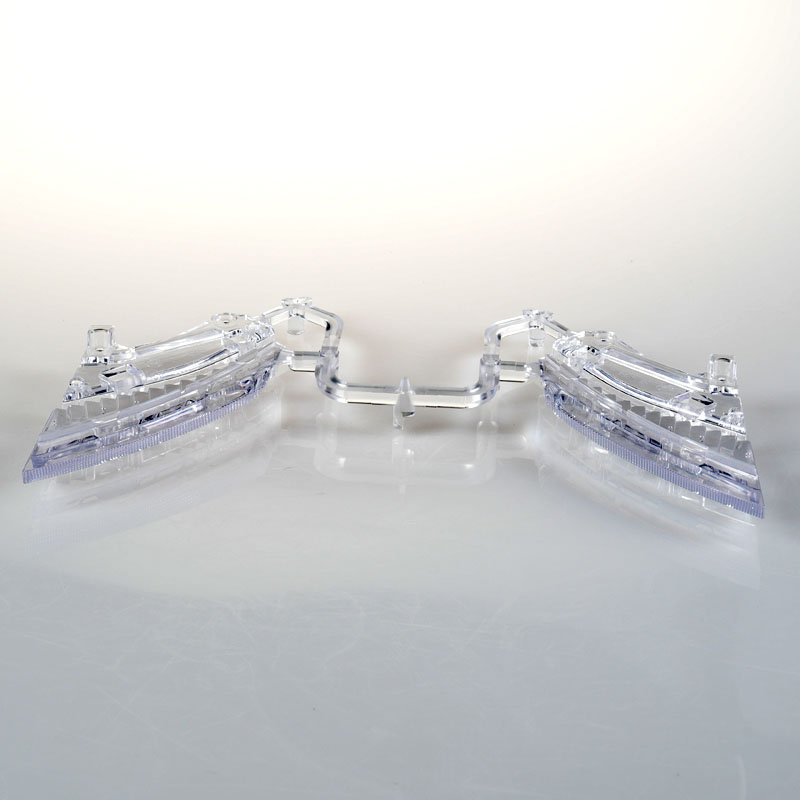
Front view of the assembly, showing the symmetry of the two blades and the connecting bridge.
How the Ribbed Surface Spreads the Light
An LED is a point source. If the guide were a plain clear bar, the end nearest the LED would glow hard and the far end would fade out. The faceted ribs molded into the blade surface break that gradient up: each facet picks up part of the travelling light and redirects it out through the blade, so the brightness the driver behind sees is spread along the length instead of piling up at one spot.
That puts rib geometry and wall thickness on the same drawing, and they have to be read together. Where the wall runs thicker, light travels further before it escapes, so that zone reads brighter. Uniform wall across the blade is what keeps the lit appearance even. It is also why a thickness variation of only a few percent is worth arguing about on this kind of part, when the same variation on a housing would be ignored.
Tooling a Long, Thin, Clear Part
The blades are long relative to their thickness, which is the classic recipe for filling trouble and warpage. The gate sits at the far end of the flow path so the melt travels the full length and packing pressure reaches the whole blade. Gating from the middle would put a weld line somewhere in the visible area, and in a clear part a weld line lights up as a dark band the moment the lamp is switched on.
The optical faces are polished to a mirror finish, because any mark left in the steel is reproduced on the part and reads as a streak when lit. Venting has to run along the thin ribs and around the curved arm, or the last region to fill traps air and shorts out. Shrinkage and warpage get the usual treatment for a long flat part: balanced cooling, even packing, and enough cooling time for the arm and the post features to set properly before ejection.
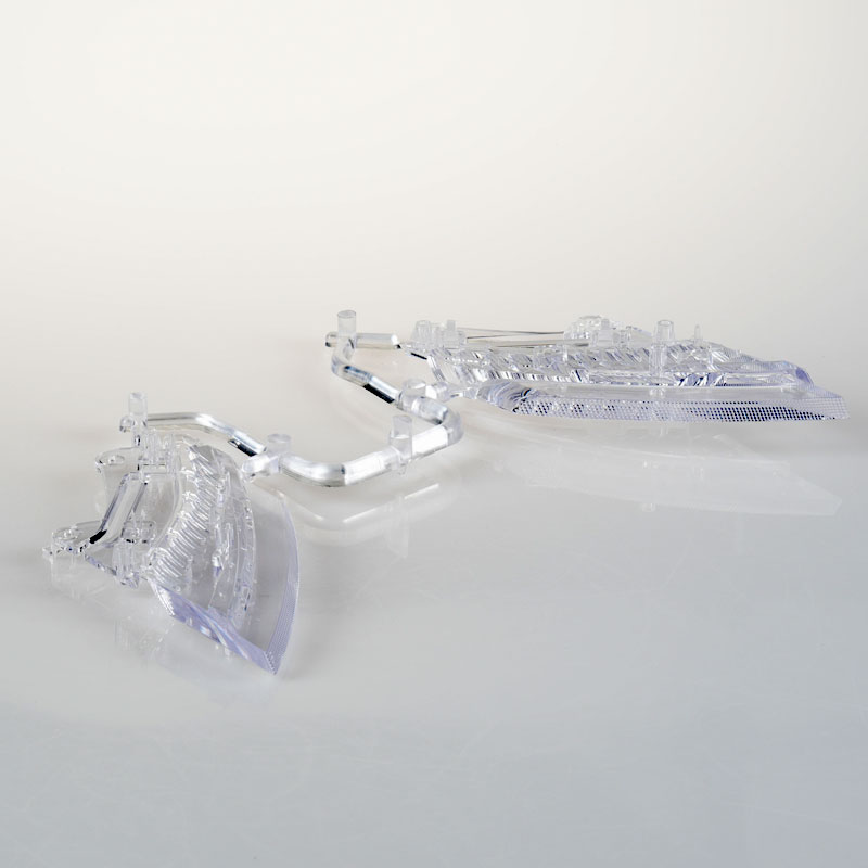
Low side view of the blade profile and the curved arm that carries light between the two guides.
Positioning Features and Assembly Fit
The round posts and clip features at the ends are not trim. They hold the guide a fixed distance from the LED, and that distance decides how much light actually couples into the blade. A guide sitting half a millimetre off its seat reads dimmer or patchier than the one beside it, and on a pair of taillights the difference is obvious at a glance.
Because the posts are molded in the same shot as the optical surfaces, their positions come out of the same tool and repeat shot after shot. That is easier to live with than a part that has to be nudged into position by hand at final assembly, especially once volumes climb past a few thousand sets.
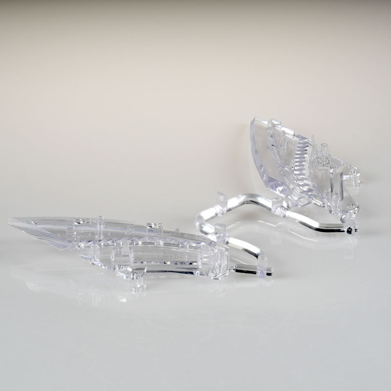
Top view of the ribbed optical surface, with the molded positioning posts visible at both ends.
What Gets Checked on a Clear Lamp Part
Dimensional report on the post and clip positions, plus a profile check along the blade. Transmission and haze measured on a sample from the lot. A lit check, where the guide is fitted to an LED and photographed, which is the only reliable way to catch flow marks, weld lines and thickness problems that a calliper will never find. Where the customer specification calls for it, a UV or weathering exposure test is added on top.
Information to Confirm Before Starting a Light Guide Project
The lamp housing drawing and the LED position, so the blade geometry and post layout can be checked against the real assembly rather than assumed.
Resin preference or specification, PMMA or PC, plus any automotive material approval the program requires.
The lit appearance target, ideally a reference sample or a written brightness uniformity requirement.
Whether the posts, clips and any secondary overmolding should come out in the same shot or be handled separately.
Expected annual volume, so cavity count and tooling investment can be sized without overspending.
Kunshan Maifeng Precision Industry Co., Ltd. reviews light guide and lamp part designs before quoting, builds the injection molds in house, and molds single-color and dual-color parts on 36 machines from 90 to 700 tons. Send us the housing drawing, the LED position and the resin specification, and we will come back with a molding feasibility comment and a tooling proposal.
Company Profile
About Us
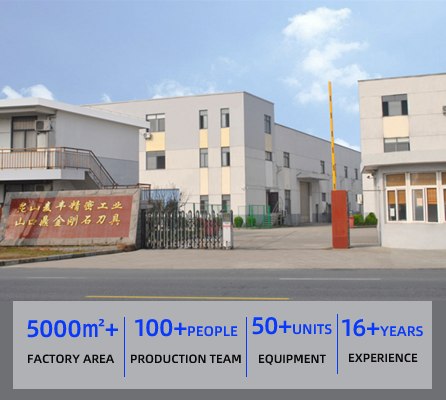
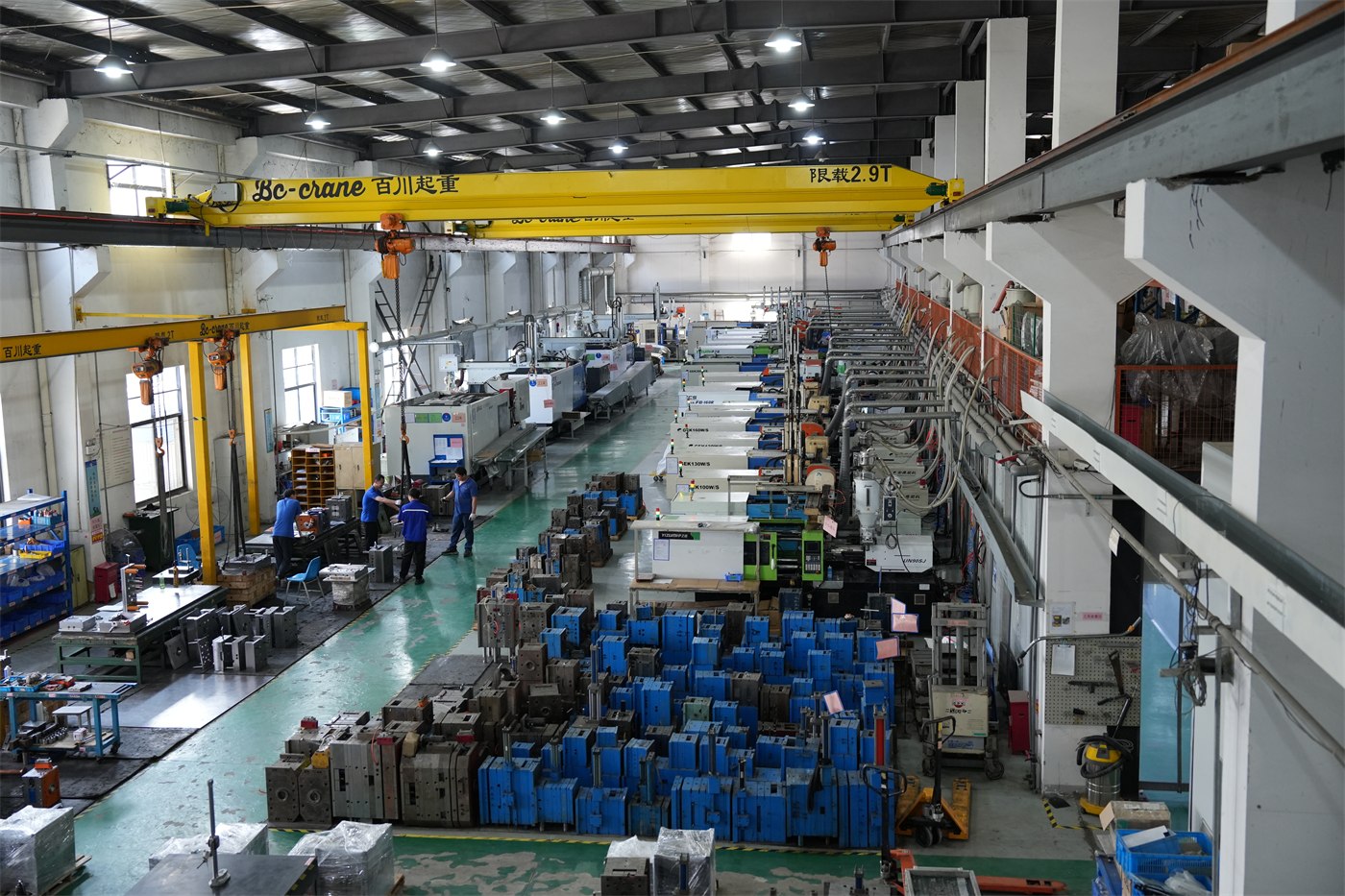
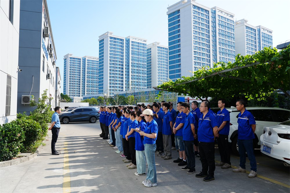
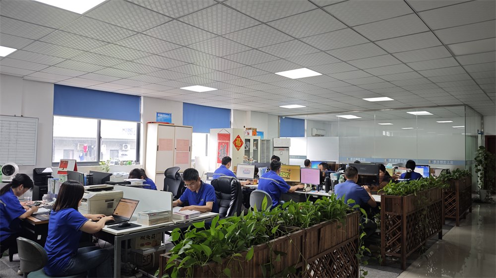
Kunshan Maifeng Precision Industry Co., Ltd. (MIF) has an investment of RMB 35 million and an independent factory of more than 5,000 m². The company operates 36 single- and dual-color injection molding machines from 90 to 700 tons, together with more than 50 sets of mold manufacturing and processing equipment. Our service, management and production team includes over 100 people.
Our parent company was established in 2008. We provide product design, mold design and manufacturing, injection molding and product assembly services for custom plastic parts, supporting both domestic and international customers.
1. Product Design Product structure design and optimization based on customer drawings and samples.
2. Mold Design Mold design developed around product geometry, material and production requirements.
3. Mold Manufacturing Machining, polishing, fitting and assembly for custom injection molds.
4. Injection Molding Single- and dual-color injection molding for project and order requirements.
5. Product Assembly Supporting assembly services for molded plastic components.
Custom glossy black PC protective cover for lawn mowers: an open-ring shell with snap clips molded in one shot and a class-A face that survives stones, sun and cleaning.
Custom PC light-diffusion tail light grille for lawn mowers: an even light band, a ribbed outer face, a sealed fixing flange and an optical surface finished to the agreed polish.
Custom clear PC tail light strip for mowers and outdoor equipment: compound curve, uniform wall, polished optical face and colour matched to your chip.
PC+ABS automotive wireless charging housing with an open coil window, four mounting ears and a stiffening rib, molded, inspected and packed for console assembly.
PC lawn mower tail light grille produced through custom mold development, precision injection molding and strict quality control for demanding outdoor applications.
PP handles and plastic parts for a 3rd generation magnetic wall mounted toilet brush, produced at Maifeng Precision through custom mold design, injection molding and careful inspection.
ABS nasal irrigator outer housing produced with custom multi-cavity molds, precision injection molding, careful trimming and dust-free packaging for personal care brands.
ABS nasal irrigator base produced with custom mold design, precision injection molding, strict inspection and dust-free packaging for personal care and medical device assemblies.
No matter what your automotive needs may be, we’re here to help. Contact us today to learn more about our
services and how we can assist you with all of your needs.
ISO 13485-certified medical injection molding in Class 10,000/100,000 cleanrooms: 36 single and dual-color machines, proven medical cases and trusted partners.
One-stop cup and bottle molding: dual-color lids, tea-separation cups and handles, QS food-contact licensed production with proven cases for global brands.
Contact Us
To grow into a top global mold & injection molding supplier
To grow into a top global mold & injection molding supplier, specializing in differentiated custom parts. We focus on structural development, streamlined production and consistent quality supply.






 Chinese
 English