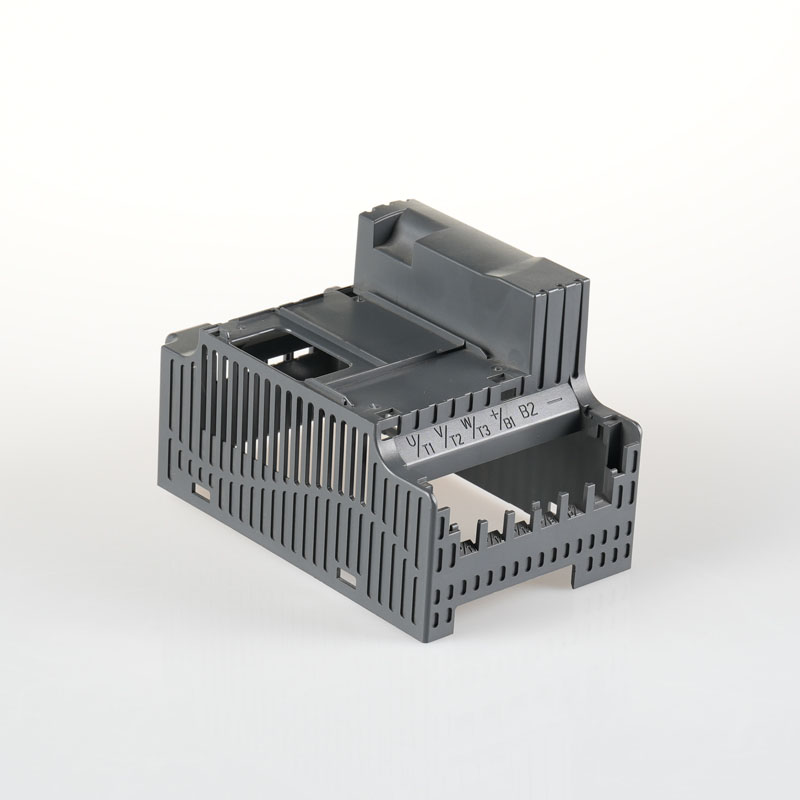
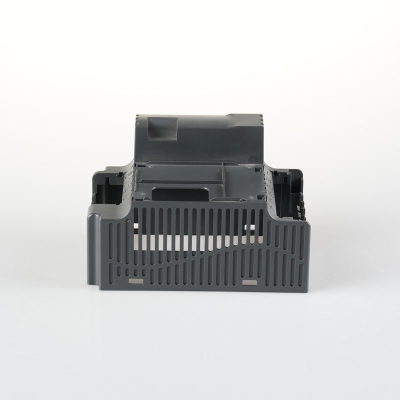
A molded front cover can look straightforward in a CAD model, yet several details determine whether it will move smoothly from tooling to repeat production. Gate balance, cosmetic surfaces, local undercuts, wall-thickness transitions, venting and ejection all need to be resolved before steel is cut. The DFM review for the frequency inverter front cover is a practical example of how these decisions can be brought forward instead of being left for repeated mold trials.
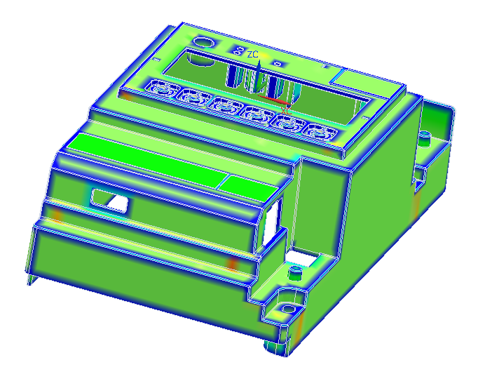
The component is specified in PC/ABS with a nominal main wall thickness of about 2.0 mm. Its visible surfaces, six-button area, local ribs and assembly features create competing requirements: the part needs complete filling and stable release while maintaining an appearance standard that can be agreed before tooling begins.
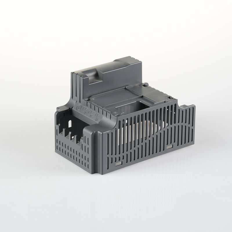
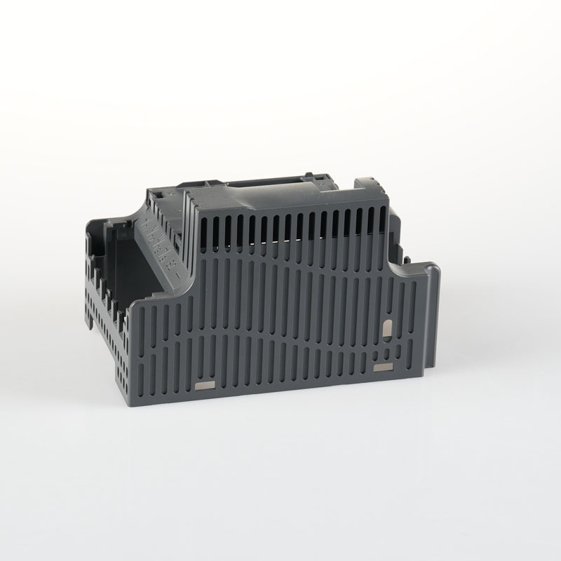
Exterior CAD view of the frequency inverter front cover used for the DFM review.
DFM Starts With Manufacturing Risk, Not Just Moldability
A useful DFM review goes beyond confirming that a part can be molded. It identifies where the proposed design may create pressure loss, visible gate vestige, sink, difficult release or inconsistent assembly. For this front cover, the review focused on the relationship between the main cavity, the button details and the internal mounting geometry.
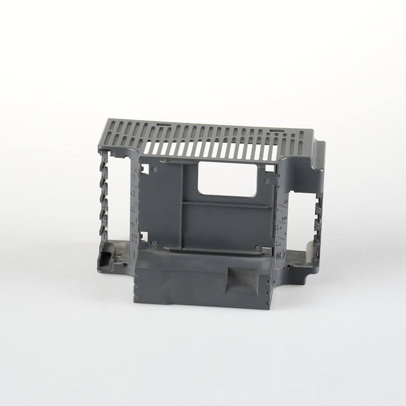
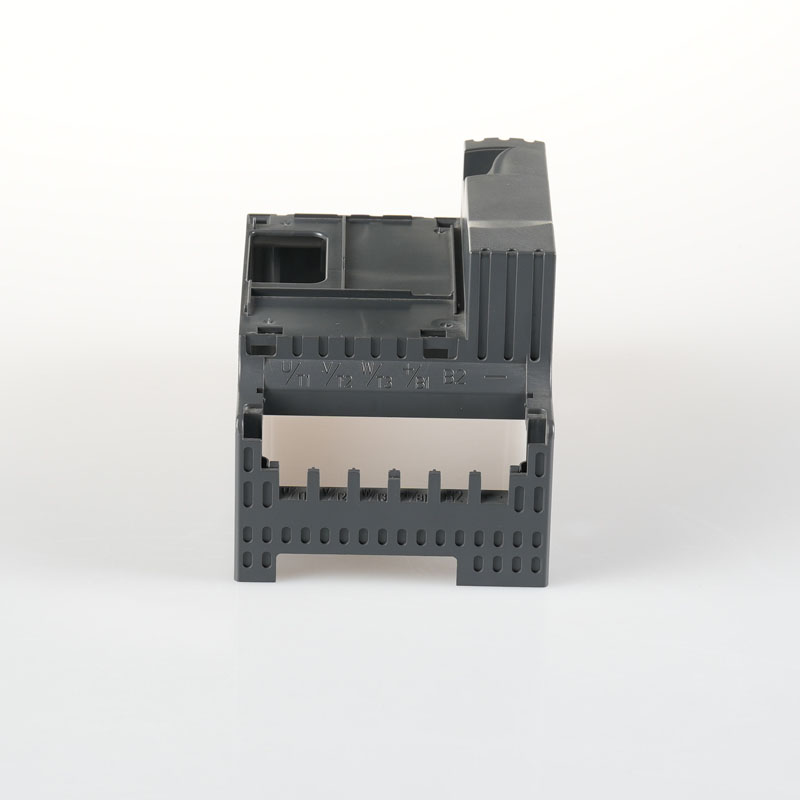
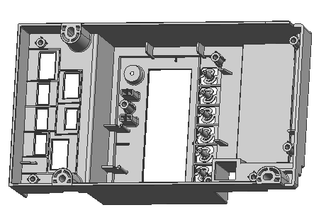
The internal view shows why the part cannot be treated as a simple cosmetic panel. Ribs, bosses, openings and the row of button features divide the flow path and create local changes in stiffness and cooling. These areas need to be evaluated together with the parting line and ejector layout.
Internal ribs, bosses and button features were reviewed together with filling, parting and ejection requirements.
Gate Optimization for the Main Body and Button Area
The original gate concept created a longer pressure path on one side of the part and left the opposite region at greater risk of incomplete filling. It also required manual trimming, which could introduce variation in gate residue and add a secondary handling step.
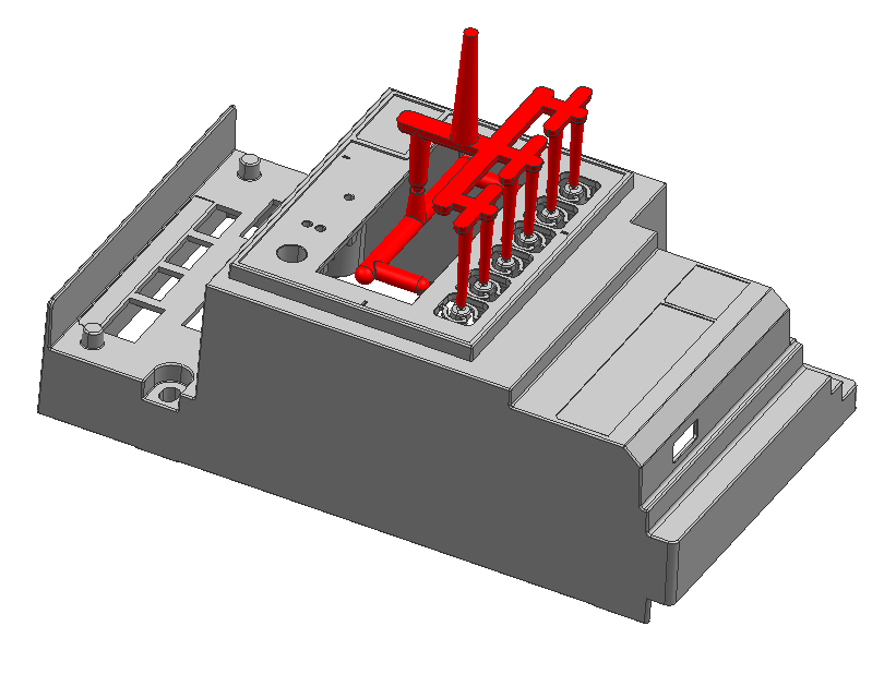
The reviewed solution uses a three-plate mold. Two overlap gates, each specified at 1 x 8 mm, feed the main body, while six independent pin-point gates with a diameter of 0.8 mm feed the button locations. Separating the button feed from the main-body flow gives those small features more direct filling support and reduces their dependence on pressure remaining after the larger areas have filled.
The DFM target is to control gate residue below 0.3 mm. This does not remove the need for trial validation, but it defines a measurable acceptance point before tooling starts and reduces reliance on uncontrolled manual trimming.
Proposed three-plate runner layout combining two main-body gates with individual gates for the six buttons.
Parting, Undercut and Appearance Boundaries
Rounded ribs on both sides of the cover created a potential undercut at the split. The proposed correction follows the main curved surface for draft and smooths the local R features so that the mold can open reliably. The review accepts an approximately 0.2 mm local step as the controlled trade-off between release, appearance and assembly.
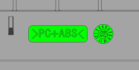
Parting lines, slider lines, ejector marks and insert boundaries were identified for confirmation before mold manufacture. This gives the customer a clear opportunity to approve where process-related lines may appear, while giving the mold maker a defined manufacturing boundary instead of an ambiguous cosmetic requirement.
Planned PC/ABS material identification and molded date marking.
Managing Wall-Thickness and Sink Risk
The DFM report identifies local differences in plastic thickness that may produce slight sink on a cosmetic PC/ABS surface. Sink is not simply a final-inspection issue. It is influenced by feature geometry, pressure transfer from the gates, cooling balance and the available packing window.
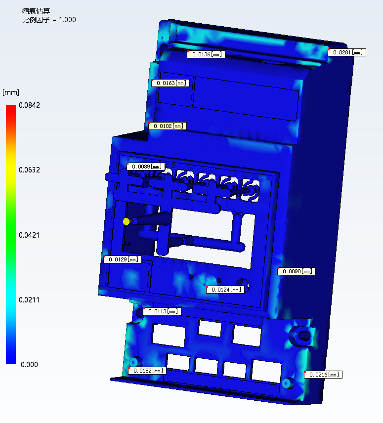
Mold-flow analysis provides an early view of filling behavior, weld lines, trapped air and estimated shrinkage. The analysis does not replace physical trials, but it helps direct attention to high-risk areas before the mold is complete. Gate positioning can then be assessed for pressure delivery across thick-to-thin transitions, while cooling and ejection can be arranged to reduce local distortion and stress marks.
Shrinkage estimate used to identify regions requiring closer tooling and process attention.
Ejection Designed Around the Part Structure
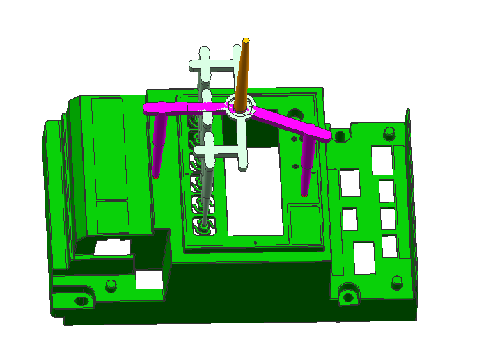
The proposed ejection system distinguishes between ejector-pin and sleeve locations. Sleeve support is added around the button tips, with the final sizes and positions confirmed during detailed mold design. The objective is not merely to push the component out of the cavity, but to place release forces close to structural support and reduce deformation, whitening or damage around the smaller features.
For a front cover that must satisfy appearance, fit and repeatable assembly at the same time, a stable release strategy can reduce trial-stage adjustment and give process engineers a clearer route to a repeatable molding window.
Ejection concept showing structural support around the main body and button region.
Turning DFM Findings Into a Tooling Plan
For the frequency inverter front cover, the DFM work converts manufacturing uncertainty into specific items that can be reviewed: gate count and size, acceptable gate residue, local parting treatment, appearance-line locations, potential sink areas and the intended ejection approach. Each item can then be carried into detailed mold design and checked during mold trials.
Kunshan Maifeng Precision supports product structure review, mold design and manufacturing, injection molding and product assembly. For a similar enclosure or front-cover project, providing the 3D data, material specification, cosmetic requirements, mating-part information and expected production volume gives the engineering team a practical basis for DFM evaluation.
Company Profile
About Us
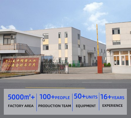
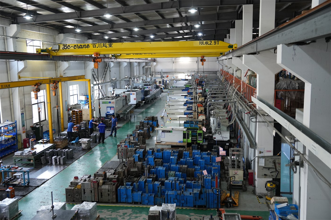
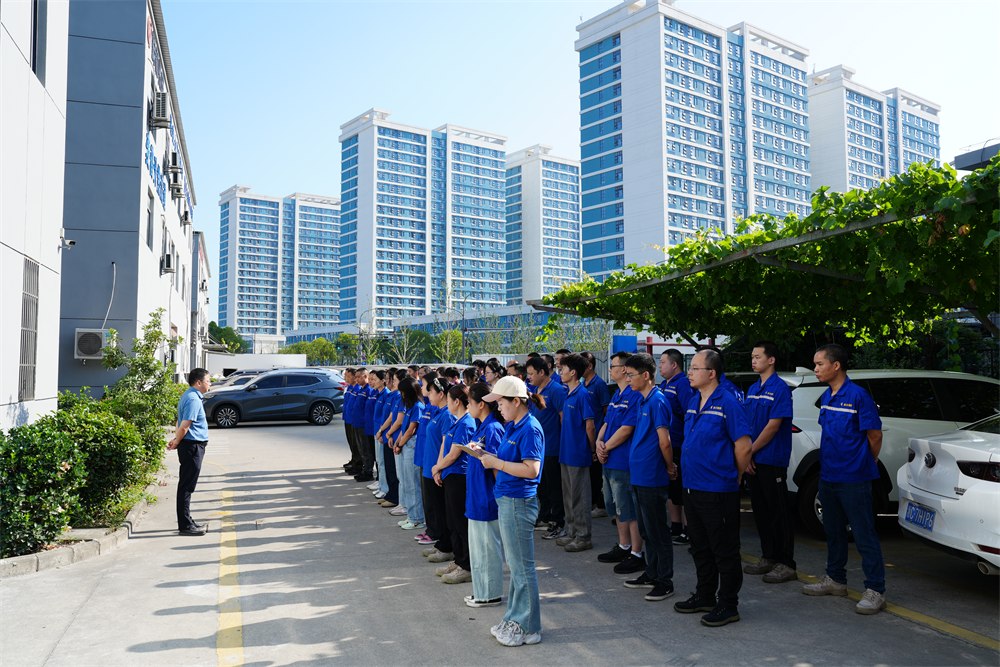
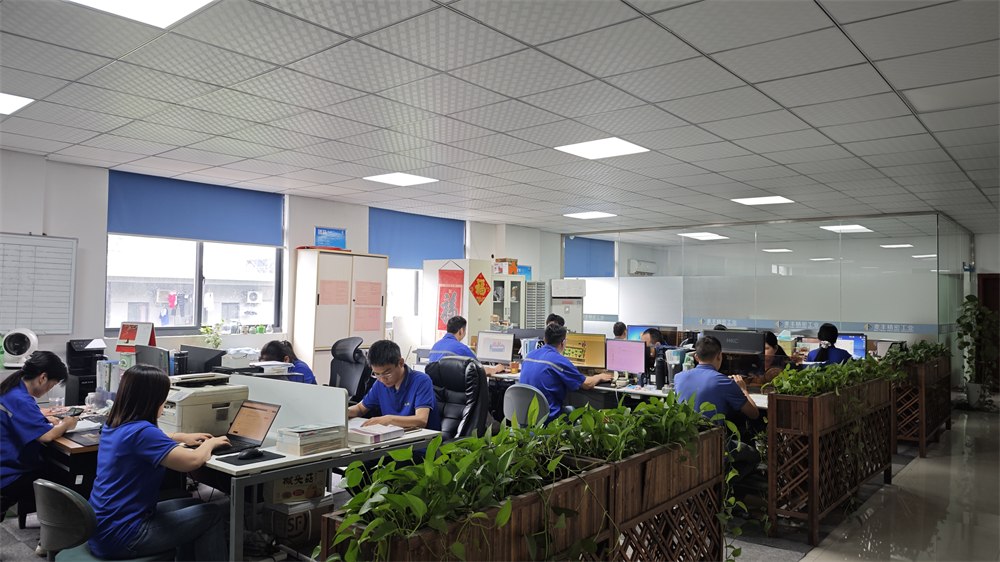
Kunshan Maifeng Precision Industry Co., Ltd. (MIF) has an investment of RMB 35 million and an independent factory of more than 5,000 m². Our manufacturing resources include 36 single- and dual-color injection molding machines from 90 to 700 tons and more than 50 sets of mold manufacturing and processing equipment. Supported by a service, management and production team of over 100 people, we provide product design, mold design and manufacturing, injection molding, and product assembly. Our parent company was established in 2008.
1. Product Design
Product structure design and optimization based on customer drawings and samples.
2. Mold Design
Mold concepts developed around product requirements, material and production needs.
3. Mold Manufacturing
Machining, polishing, assembly and related processes for custom molds.
4. Injection Molding
Single- and dual-color molding capabilities for custom production.
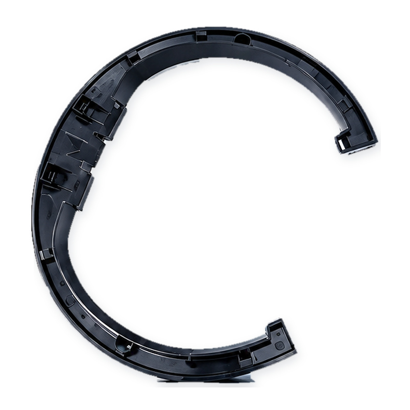
Custom glossy black PC protective cover for lawn mowers: an open-ring shell with snap clips molded in one shot and a class-A face that survives stones, sun and cleaning.
Custom PC light-diffusion tail light grille for lawn mowers: an even light band, a ribbed outer face, a sealed fixing flange and an optical surface finished to the agreed polish.
Custom clear PC tail light strip for mowers and outdoor equipment: compound curve, uniform wall, polished optical face and colour matched to your chip.
PC+ABS automotive wireless charging housing with an open coil window, four mounting ears and a stiffening rib, molded, inspected and packed for console assembly.
PC lawn mower tail light grille produced through custom mold development, precision injection molding and strict quality control for demanding outdoor applications.
PP handles and plastic parts for a 3rd generation magnetic wall mounted toilet brush, produced at Maifeng Precision through custom mold design, injection molding and careful inspection.
ABS nasal irrigator outer housing produced with custom multi-cavity molds, precision injection molding, careful trimming and dust-free packaging for personal care brands.
ABS nasal irrigator base produced with custom mold design, precision injection molding, strict inspection and dust-free packaging for personal care and medical device assemblies.
No matter what your automotive needs may be, we’re here to help. Contact us today to learn more about our
services and how we can assist you with all of your needs.
ISO 13485-certified medical injection molding in Class 10,000/100,000 cleanrooms: 36 single and dual-color machines, proven medical cases and trusted partners.
One-stop cup and bottle molding: dual-color lids, tea-separation cups and handles, QS food-contact licensed production with proven cases for global brands.
Contact Us
To grow into a top global mold & injection molding supplier
To grow into a top global mold & injection molding supplier, specializing in differentiated custom parts. We focus on structural development, streamlined production and consistent quality supply.






 Chinese
 English